ChevyParts
My Garage
My Account
Cart
OEM Chevrolet Trailblazer Universal Joint
U-Joint- Select Vehicle by Model
- Select Vehicle by VIN
Select Vehicle by Model
orMake
Model
Year
Select Vehicle by VIN
For the most accurate results, select vehicle by your VIN (Vehicle Identification Number).
2 Universal Joints found


Chevrolet Trailblazer Universal Joints Part Number: 23104840
$36.45 MSRP: $88.98You Save: $52.53 (60%)


Chevrolet Trailblazer Universal Joints Part Number: 89059111
$163.83 MSRP: $273.43You Save: $109.60 (41%)Ships in 1-2 Business Days
Chevrolet Trailblazer Universal Joint
Want to cut long-term maintenance and repair costs? Choose OEM Universal Joint. Those parts deliver top durability you can trust. On our site, you'll find a huge catalog of genuine Chevrolet Trailblazer parts. Prices are unbeatable, so you can keep more in your pocket. Every OEM Chevrolet Trailblazer Universal Joint includes a manufacturer's warranty. You can also get an easy return policy that keeps buying risk free. Fast delivery, get your car on the road quickly. It's simple to search, compare, and order. Stop guessing about quality or fit. Order today and save with parts that last.
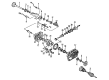
The Universal Joint in Chevrolet Trailblazer is essential in transmitting the rotation of the driveshaft to the differential so as to facilitate movement depending on the status of the suspension system of the vehicle. This joint allows the driveshaft to rotate as needed when angles of the components connected to the driveshaft are distinct from each other. Usually, there is the Universal Joint at the front part of the GM Chevrolet Trailblazer driveshaft coupled with the transmission slip yoke, and at the other end there is the differential yoke or flange. The Universal Joint, which is made out a cross and needle bearings enclosed in steel cups that are harden, has the capability of withstanding wear and tear. Factory Universal Joints are greased and shipped to us while Universal Joints have a grease zerk that can be refilled after a while. Eventually, they develop problems such as noises and vibrations, hence requiring an inspection for replacement for Chevrolet Trailblazer's normal functioning.
Chevrolet Trailblazer Universal Joint Parts Questions & Experts Answers
- Q: What tools are needed to service and repair the universal joint with an external snap ring on Chevrolet Trailblazer?A:Repairing a Universal Joint with an external snap ring requires use of these tools: the proper tools for this task include u-joint bearing separator (J 9522-3) together with u-joint bearing spacer remover (J 9522-5). U-joint bearing separator (J 9522-3) and u-joint bearing spacer remover (J 9522-5). Set the propeller shaft horizontally on a press for support while maintaining the tubing out of vise contact to protect it from damage. Make identifying marks on the propeller shaft to show its connection points with the transmission and rear axle assembly. Use pliers to pinch snap ring ends for disassembly and tap the cup end lightly to reduce pressure when needed. Free the supporting surface of the Universal Joint by using a 30 mm (1-1/8 inch) hex head socket or a 27 mm (1-1/16 inch) socket before using the u-joint bearing separator (J 9522-3) for bearing cup removal from the yoke ear. To press out the bearing cup which will not dislodge completely a u-joint bearing spacer remover (J 9522-5) needs to be placed between the bearing cup and the seal. The rotating propeller shaft exerting pressure on the opposing bearing cup requires you to note the Slip Yoke position for reinstallation. Examine both the bearing cup bores and retaining ring grooves for cleanliness while looking for any imperfections. Remove the cross and discarded Universal Joint parts from the assembly. Position a bearing cup on one yoke side followed by the cross assembly then apply pressure until the cup rests flush with the ear. Move through this process again on the different side of the yoke while checking that all trunnions remain correctly oriented. Run the press tool until you can see the retainer groove before you position the bearing retainer. Keep pressing until both retainers securely lock into place. The dead blow hammer can lightly press the yoke when needed to help with retainer placement while chassis grease applied on the bearing cup edges will assist with correct seating.

Related Chevrolet Trailblazer Parts
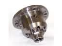 Chevrolet Trailblazer Differential
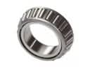 Chevrolet Trailblazer Differential Bearing
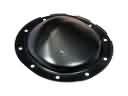 Chevrolet Trailblazer Differential Cover
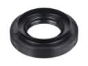 Chevrolet Trailblazer Differential Seal
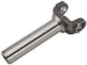 Chevrolet Trailblazer Driveshaft Yokes
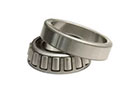 Chevrolet Trailblazer Pinion Bearing
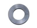 Chevrolet Trailblazer Pinion Washer
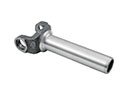 Chevrolet Trailblazer Slip Yoke
 Chevrolet Trailblazer Wheel Seal