ChevyParts
My Garage
My Account
Cart
OEM Chevrolet Venture Rear Crossmember
Rear Suspension Crossmember- Select Vehicle by Model
- Select Vehicle by VIN
Select Vehicle by Model
orMake
Model
Year
Select Vehicle by VIN
For the most accurate results, select vehicle by your VIN (Vehicle Identification Number).
1 Rear Crossmember found

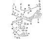
Chevrolet Venture Suspension Crossmember, Rear Part Number: 15127512
Chevrolet Venture Rear Crossmember
Want to cut long-term maintenance and repair costs? Choose OEM Rear Crossmember. Those parts deliver top durability you can trust. On our site, you'll find a huge catalog of genuine Chevrolet Venture parts. Prices are unbeatable, so you can keep more in your pocket. Every OEM Chevrolet Venture Rear Crossmember includes a manufacturer's warranty. You can also get an easy return policy that keeps buying risk free. Fast delivery, get your car on the road quickly. It's simple to search, compare, and order. Stop guessing about quality or fit. Order today and save with parts that last.
Chevrolet Venture Rear Crossmember Parts and Q&A
- Q: How to replace the Rear Crossmember on Chevrolet Venture?A:Start by lifting the vehicle before supporting it with tools then eliminate the wheel and tire assembly. The support system involves placing a utility stand under the rear Differential carrier for the removal of all Rear Crossmember mounting bolts. First mark the frame locations of the Rear Crossmember mount before you remove the rear suspension knuckle. First disconnect the wheel speed sensor harness from both the lower Control Arm and the Rear Crossmember. After that remove the rivets connecting the park brake cable to the Rear Crossmember. A utility jack supports the Rear Crossmember while you take out the Rear Crossmember mounting bolts to put the crossmember into position. After removing the rear stabilizer shaft you should proceed to detach the upper and lower rear control arms from the Rear Crossmember before collecting the Tie Rods from their position on the crossmember. The installation process begins with Tie Rod attachment to the crossmember followed by rear axle control arms installation onto the crossmember then the stabilizer shaft installation completes the process. Position the raised crossmember to match the frame scribe marks before inserting Rear Crossmember bolts which should be torqued between 115-145 n.m (96 lb ft). Fasten the rear Differential carrier mounting bolts while torquing each one to 37 n.m (50 lb ft). First position the Parking Brake Cable onto the Rear Crossmember before you wire up the wheel speed sensor harness to both Rear Crossmember and lower Control Arm and then place the rear suspension knuckle into position. After installation replace the tire and wheel before slowly lowering the vehicle.

Related Chevrolet Venture Parts
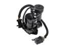 Chevrolet Venture Air Suspension Compressor
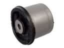 Chevrolet Venture Axle Beam Mount
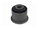 Chevrolet Venture Axle Pivot Bushing
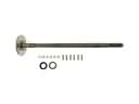 Chevrolet Venture Axle Shaft
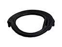 Chevrolet Venture Coil Spring Insulator
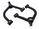 Chevrolet Venture Control Arm
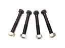 Chevrolet Venture Control Arm Bolt
 Chevrolet Venture Control Arm Bushing
 Chevrolet Venture Suspension Strut Rod
 Chevrolet Venture Sway Bar Bracket
 Chevrolet Venture Sway Bar Kit
 Chevrolet Venture Sway Bar Link