ChevyParts
My Garage
My Account
Cart
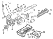
OEM GMC Sierra 3500 Classic Intake Manifold
Engine Intake Manifold- Select Vehicle by Model
- Select Vehicle by VIN
Select Vehicle by Model
orMake
Model
Year
Select Vehicle by VIN
For the most accurate results, select vehicle by your VIN (Vehicle Identification Number).
7 Intake Manifolds found


GMC Sierra 3500 Classic Intake Manifold Part Number: 97363572
$87.21 MSRP: $136.61You Save: $49.40 (37%)Ships in 1-3 Business Days

GMC Sierra 3500 Classic Intake Manifold Part Number: 97363571
$90.50 MSRP: $141.75You Save: $51.25 (37%)Ships in 1-3 Business Days


GMC Sierra 3500 Classic Manifold Part Number: 97364407

GMC Sierra 3500 Classic Intake Manifold Part Number: 97363569

GMC Sierra 3500 Classic Manifold Part Number: 97363568

GMC Sierra 3500 Classic Intake Manifold Part Number: 19418186

GMC Sierra 3500 Classic Intake Manifold Part Number: 12581115
GMC Sierra 3500 Classic Intake Manifold
Want to cut long-term maintenance and repair costs? Choose OEM Intake Manifold. Those parts deliver top durability you can trust. On our site, you'll find a huge catalog of genuine GMC Sierra 3500 Classic parts. Prices are unbeatable, so you can keep more in your pocket. Every OEM GMC Sierra 3500 Classic Intake Manifold includes a manufacturer's warranty. You can also get an easy return policy that keeps buying risk free. Fast delivery, get your car on the road quickly. It's simple to search, compare, and order. Stop guessing about quality or fit. Order today and save with parts that last.
GMC Sierra 3500 Classic Intake Manifold Parts Questions & Experts Answers
- Q: How to replace the intake manifold on LH6, LMG, LY5, and L76 engines on GMC Sierra 3500 Classic?A:Engineers should start replacement of the Intake Manifold on lh6, lmg, ly5, and l76 engines by dislodging the air cleaner outlet duct followed by generator removal and engine harness retainer nut extraction. The next step involves eliminating the engine harness retainer from its stud and locator. Remove the electrical harness connectors from the following components: evap canister purge solenoid , manifold absolute pressure (MAP) sensor , ignition coil harness , left side Fuel Injectors , throttle actuator , engine coolant temperature (ECT) sensor , and right side fuel injectors . Disassemble the engine harness clips (4, 6, 1) before securing each harness branch neatly out of reach. The process requires you to relocate the Brake Booster Vacuum Hose while disconnecting the evap canister purge tube and fuel feed line . Reconnect the Brake Booster Vacuum Hose and clamp before you put new Intake Manifold gaskets (514) in place. Position the Intake Manifold (500) while keeping the engine harness clear from obstructions. To replace the manifold remove first the Brake Booster Vacuum Hose from the Intake Manifold nipple along with the upper Intake Manifold cover nut then upper Intake Manifold cover before extracting the MAP Sensor and evap tube. Before proceeding discard the Throttle Body gasket and Fuel Injector lower o-ring seals while removing the Throttle Body and Fuel Rail. The installation process includes fitting the Brake Booster Vacuum Hose nipple to the new Intake Manifold followed by the application of clean engine oil to new Fuel Injector lower o-ring seals and the performance of forceful down pressure on both ends of the rail to set the injectors. Attach the Fuel Rail first and tighten its bolts to 10 n.m (89 lb in) before installing the Throttle Body with a new gasket along with the evap tube and purge solenoid. Place lubricant on the MAP Sensor seal before installing the MAP Sensor with its retainer followed by the upper Intake Manifold cover until it reaches a snug fit. First reconnect the Brake Booster Vacuum Hose then install new Intake Manifold gaskets and position the Intake Manifold (500) with attention to engine harness clearance. Position the Intake Manifold (500) while ensuring the engine harness remains clear then tighten its bolts (512) in sequence to 5 n.m (44 lb in) for the first pass up to 10 n.m (89 lb in) for the final pass. Finish the installation by connecting the pcv hose along with the fuel feed line as well as the evap canister purge tube . Finally reattach the loose engine harness while also reconnecting the ect sensor . Secure clips 1 and 4 and 6 of the engine harness while following specifications to install the retainer and fasten the nut with 5 n.m (44 lb in) torque setting before reattaching the generator and air cleaner outlet duct.

Related GMC Sierra 3500 Classic Parts
 GMC Sierra 3500 Classic Air Filter
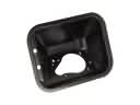 GMC Sierra 3500 Classic Fuel Filler Housing
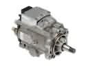 GMC Sierra 3500 Classic Fuel Injection Pump
 GMC Sierra 3500 Classic Fuel Pump
 GMC Sierra 3500 Classic Fuel Tank
 GMC Sierra 3500 Classic Fuel Tank Sending Unit
 GMC Sierra 3500 Classic Fuel Tank Strap
 GMC Sierra 3500 Classic Gas Cap
 GMC Sierra 3500 Classic Intake Manifold Gasket
 GMC Sierra 3500 Classic Mass Air Flow Sensor
 GMC Sierra 3500 Classic Throttle Body
 GMC Sierra 3500 Classic Turbocharger