ChevyParts
My Garage
My Account
Cart
OEM 2000 Chevrolet Prizm Front Cross-Member
Front Engine Cross Member- Select Vehicle by Model
- Select Vehicle by VIN
Select Vehicle by Model
orMake
Model
Year
Select Vehicle by VIN
For the most accurate results, select vehicle by your VIN (Vehicle Identification Number).
1 Front Cross-Member found

2000 Chevrolet Prizm Engine Cradle Part Number: 89027243
Product Specifications- Other Name: Crossmember, Intermediate
- Position: Front
- Replaces: 94856306
- Item Weight: 23.80 Pounds
- Item Dimensions: 40.4 x 20.6 x 11.2 inches
- Condition: New
- Fitment Type: Direct Replacement
- SKU: 89027243
- Warranty: This genuine part is guaranteed by GM's factory warranty.
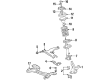
2000 Chevrolet Prizm Front Cross-Member
With a comprehensive array of OEM 2000 Chevrolet Prizm Front Cross-Member, from fuel pumps to door handles, our website is a one-stop-shop for your needs. All our genuine 2000 Chevrolet Prizm Front Cross-Member are backed by the manufacturer's warranty and are offered at competitive prices in the market. Rest assured, you can shop with complete confidence.
2000 Chevrolet Prizm Front Cross-Member Parts Questions & Experts Answers
- Q: How to replace the Front Cross-Member on 2000 Chevrolet Prizm?A: To replace the front suspension crossmember, it is necessary to first install the engine support fixture and lift the vehicle. Take away the front tire and wheel assembly, and then the 3 nuts (12, 15, 16) from the crossmember, and jack up the assembly. Remove the 2 nuts (4, 6) and the front suspension crossmember brace from the bracket studs (3, 7) and then the bolt and the 2 nuts on the left and right control arms. Next, unscrew the 5 (2, 3, 8, 9, 1) and the stud 7 from the right, and the 5 (2,3,5,6,7) and the stud 7 from the left. Unscrew the 2 bolts (5, 10) securing the engine splash shields to the trans support, the front transaxle mount to the trans support held with 2 bolts (3, 4) and the 2 bolts (1, 2) hold the trans support to vehicle. Lower the jack to get rid of the front suspension crossmember and trans support , 2 front control arms (8, 9) and front stabilizer shaft if available. If there are, remove nut and stabilizer shaft insulator clamp from the right side of the crossmember, nut and Control Arm Bracket from the right side and stabilizer shaft links from the control arms. Repeat this on the left, taking off the nut and Control Arm Bracket, followed by the bolt from both sides. Finally, unscrew the bolt and the nut so that the trans support can be separated from the crossmember. For installation, locate the trans support and attach it to the front suspension crossmember provided with nut and bolt and tighten to 60 nm (45 ft. Lbs.) install the front Control Arm on both sides but do not tighten then secure the Control Arm Bracket with respective nuts (4,12)at 19 nm (14ft.lbs. ). As applicable, position and tighten the stabilizer shaft insulator clamps to 19 nm (14 ft. Lbs.). Lift the components as a unit and bolt secure the trans support to vehicle with bolts (1, 2) but for the bolt do not tighten. Install the front transaxle mount bolts (3, 4) to 64 nm (47 ft. Lbs.), then to the engine splash shield bolts (5, 10) to 10 nm (89 inch lbs.). Position the studs (3, 7) and tighten to 147 nm (109 ft. Lbs.) and then bolt (2, 3, 5, 6, 7) on lh side and (2, 3, 8,9,11) on rh side without tightening. Make sure to secure the right front Control Arm with the 2 nuts and bolt and tighten it to 142 nm (105 ft. Lbs.) and the same goes for the left front Control Arm. Remove the jack and install the 3 nuts (12, 15,16) to the cross member and tighten at 57 nm (42 ft. Lbs.); then, the front suspension cross member brace and 2 nuts (4, 6) at 69 nm (51 ft.lbs). Replace the tire and wheel assembly, lower the vehicle and ensure the weight is applied to the tires. Lift the vehicle again, press front bumper downward 3 times to stabilize suspension and torque the trans support bolts (1, 2) to 60nm (45 ft. Lbs.), the inside bolt for left Control Arm to 175nm (129 ft. Lbs.), and bolt the front bolts (1, 2, 3) for left Control Arm and crossmember to 215nm (158 ft. Lbs.) and 225nm (167 ft. Lbs.) respectively. Torque the outer bolt 147 nm (109 ft. Lbs) and the rear bolt 123 nm (91 ft. Lbs). Depending on its necessity, you should just hold the left stabilizer shaft link stud using the 5mm hex wrench to tighten the nut at 44nm (33 ft. Lbs.). Repeat the torque process on the right side, followed by lowering the vehicle, as well as removing the engine support fixture to measure the wheel alignment and adjusting as required.
Related 2000 Chevrolet Prizm Parts
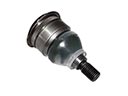 2000 Chevrolet Prizm Ball Joint
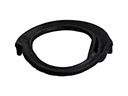 2000 Chevrolet Prizm Coil Spring Insulator
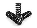 2000 Chevrolet Prizm Coil Springs
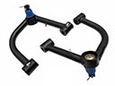 2000 Chevrolet Prizm Control Arm
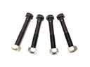 2000 Chevrolet Prizm Control Arm Bolt
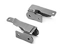 2000 Chevrolet Prizm Control Arm Bracket
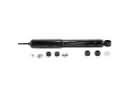 2000 Chevrolet Prizm Shock Absorber
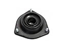 2000 Chevrolet Prizm Shock And Strut Mount
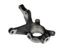 2000 Chevrolet Prizm Steering Knuckle
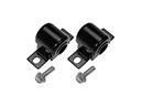 2000 Chevrolet Prizm Sway Bar Bushing
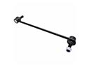 2000 Chevrolet Prizm Sway Bar Link
 2000 Chevrolet Prizm Wheel Seal