ChevyParts
My Garage
My Account
Cart
OEM 2005 Chevrolet Corvette Front Cross-Member
Front Engine Cross Member- Select Vehicle by Model
- Select Vehicle by VIN
Select Vehicle by Model
orMake
Model
Year
Select Vehicle by VIN
For the most accurate results, select vehicle by your VIN (Vehicle Identification Number).
1 Front Cross-Member found

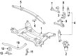
2005 Chevrolet Corvette Engine Cradle Part Number: 20850582
$251.99 MSRP: $376.74You Save: $124.75 (34%)Product Specifications- Other Name: Crossmember; Crossmember, Front Frame Cross Member
- Position: Front
- Replaces: 15864492, 15215882
- Item Weight: 38.20 Pounds
- Item Dimensions: 37.8 x 24.7 x 10.2 inches
- Condition: New
- Fitment Type: Direct Replacement
- SKU: 20850582
- Warranty: This genuine part is guaranteed by GM's factory warranty.
2005 Chevrolet Corvette Front Cross-Member
With a comprehensive array of OEM 2005 Chevrolet Corvette Front Cross-Member, from fuel pumps to door handles, our website is a one-stop-shop for your needs. All our genuine 2005 Chevrolet Corvette Front Cross-Member are backed by the manufacturer's warranty and are offered at competitive prices in the market. Rest assured, you can shop with complete confidence.
2005 Chevrolet Corvette Front Cross-Member Parts and Q&A
- Q: How to replace the Front Cross-Member on 2005 Chevrolet Corvette?A: When replacing the front suspension crossmember start by unmounting the generator from its accessory bracket and then disconnect the washer pump/reservoir. The engine coolant temperature switch electrical connector and front headlamp electrical connector need to be disconnected and set aside. Support the engine with the engine support fixture (J 41803) and the universal engine support fixture (J 28467-B) before raising and supporting the entire vehicle. Start by taking off the tire and wheel assemblies then disconnect the steering linkage outer Tie Rod End stud nuts. Both the Shock Absorber solenoid electrical connector and the electronic suspension control (ESC) sensor links require detachment for this repair. First remove the stabilizer shaft before disconnecting the intermediate shaft lower coupling from the steering gear and then undo the electronic brake control module (EBCM)/brake pressure modulator valve (BPMV) bracket bolts. Finally support and relocate the ebcm/bpmv assembly with bracket against the crossmember. Disassemble the power steering fluid cooler from the crossmember while replacing the bolts securing the power steering gear. Lift the power steering gear off the crossmember after this sequence completes. The transverse spring compressor tool (J 33432-A) removes transverse springs from motor vehicles. First disconnect the lower Shock Absorber bolts installed at the lower Control Arm then remove the crossmember lower Control Arm bolts. A transmission jack goes beneath the crossmember before the engine mount lower nuts get removed alongside wheel speed sensor wiring harness disconnect and electrical harness and brake pipe clip removal from the crossmember. After removing all crossmember mounting nuts you can pull down the crossmember from the vehicle. After aligning the vehicle-mounted crossmember with the engine mount studs and frame rails' dowel pins you can begin installation. After installing new crossmember mounting nuts the technician should apply 110 n.m (81 lb ft) torque before proceeding to torque the engine mount lower nuts. Secure all wheel speed sensor wiring harness retaining clips together with the brake pipe and electrical harness to the crossmember. The transverse spring requires installation using a transverse spring compressor (J 33432-A) before installing the lower control arms and shock absorbers with 28 n.m (21 lb ft) torque on the Shock Absorber bottom mounting nuts. Begin power steering gear installation starting with tight mounting bolts to 100 n.m (74 lb ft) and finishing with bpmv bolts installation afterward. The intermediate shaft must connect to the steering gear and install the steering linkage outer tie rod ends during which time also reconnect the esc sensor links and Shock Absorber solenoid electrical connector if equipped. Lower the vehicle while placing back the stabilizer shaft and tire and wheel assemblies. Next disconnect engine support fixture (J 41803) together with universal engine support fixture (J 28467-B) before mounting back the generator and washer pump/reservoir. The last steps include reconnecting the engine coolant temperature switch electrical connector followed by the front headlamp electrical connector before connecting the negative Battery Cable then performing the vehicle front end alignment.
Related 2005 Chevrolet Corvette Parts
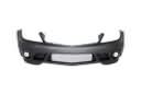 2005 Chevrolet Corvette Bumper
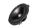 2005 Chevrolet Corvette Car Speakers
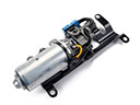 2005 Chevrolet Corvette Convertible Top Motor
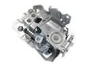 2005 Chevrolet Corvette Door Latch Assembly
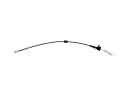 2005 Chevrolet Corvette Door Latch Cable
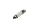 2005 Chevrolet Corvette Interior Light Bulb
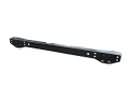 2005 Chevrolet Corvette Rear Crossmember
 2005 Chevrolet Corvette Tailgate Lock
 2005 Chevrolet Corvette Trunk Latch
 2005 Chevrolet Corvette Trunk Lid Lift Support
 2005 Chevrolet Corvette Wiper Blade
 2005 Chevrolet Corvette Wiper Motor