ChevyParts
My Garage
My Account
Cart
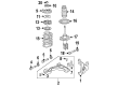
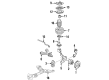
OEM Buick Park Avenue Steering Knuckle
Front Steering Knuckle- Select Vehicle by Model
- Select Vehicle by VIN
Select Vehicle by Model
orMake
Model
Year
Select Vehicle by VIN
For the most accurate results, select vehicle by your VIN (Vehicle Identification Number).
15 Steering Knuckles found


Buick Park Avenue Knuckle, Driver Side Part Number: 23127629
$268.88 MSRP: $442.93You Save: $174.05 (40%)Ships in 1-2 Business Days
Buick Park Avenue Knuckle, Passenger Side Part Number: 18060635
$164.43 MSRP: $376.96You Save: $212.53 (57%)Ships in 1-2 Business Days

Buick Park Avenue Knuckle, Driver Side Part Number: 18060634

Buick Park Avenue Spindle, Rear Driver Side Part Number: 25527483
Buick Park Avenue Spindle, Rear Passenger Side Part Number: 25527482
Buick Park Avenue Knuckle, Rear Passenger Side Part Number: 25620438
Buick Park Avenue Knuckle, Rear Driver Side Part Number: 25620437

Buick Park Avenue Knuckle, Passenger Side Part Number: 19303856
Buick Park Avenue Knuckle, Driver Side Part Number: 19303855

Buick Park Avenue Knuckle, Passenger Side Part Number: 18060601
Buick Park Avenue Knuckle, Driver Side Part Number: 18060600

Buick Park Avenue Knuckle, Passenger Side Part Number: 18060584
Buick Park Avenue Knuckle, Driver Side Part Number: 18060583
Buick Park Avenue Knuckle, Passenger Side Part Number: 18016012
Buick Park Avenue Knuckle, Driver Side Part Number: 18016011
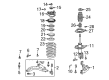
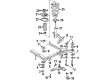
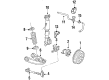
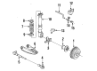
Buick Park Avenue Steering Knuckle
Want to cut long-term maintenance and repair costs? Choose OEM Steering Knuckle. Those parts deliver top durability you can trust. On our site, you'll find a huge catalog of genuine Buick Park Avenue parts. Prices are unbeatable, so you can keep more in your pocket. Every OEM Buick Park Avenue Steering Knuckle includes a manufacturer's warranty. You can also get an easy return policy that keeps buying risk free. Fast delivery, get your car on the road quickly. It's simple to search, compare, and order. Stop guessing about quality or fit. Order today and save with parts that last.
Buick Park Avenue Steering Knuckle is a part that closely associated with the company's reliability and performance aspects. Also, the Knuckle connects the suspension and the steering systems while allowing the necessary vertical and horizontal movement to respond quickly to different road conditions or driving commands. This feature is quite relevant to the Buick Park Avenue that is a full size luxury car introduced for its smooth and rather complex engineering. The Steering Knuckle is suitable for numerous models of Park Avenue; it increases the car's efficiency and safety since it provides a precise control over handling and stability. The Transition Of Buick Park Avenue Steering Knuckle From Kingpin To Ball Joint Dovering an aspect of improved automotive mechanical designing over years where the steering knuckle is a very durable component and usually lasts for the entire life of the vehicle and is only replaced in case of damage. Great emphasis should be put upon the periodicity of the checkup of the Steering Knuckle's stud bores, spindles, and bushings to enhance the performance. For instance, Buick Park Avenue can be described as a car that has a detailed history; the first generation of this model was produced in 1991 and is equipped with such features as Dynaride and 3800 OHV V6. The Steering Knuckle also has an important role in this regard; it is the component that in essence aids in the fundamental handling that the Buick Park Avenue enjoys and has given it a reputed status in the automotive domain. Undoubtedly, the Buick Park Avenue Steering Knuckle is one of the most successful collection within the Buick range due to its combination of luxury, performance, and the company's commitment to creating vehicles of high reliability.
Buick Park Avenue Steering Knuckle Parts Questions & Experts Answers
- Q: How to service and repair the steering knuckle on Buick Park Avenue?A:A technician must use the following steps to repair the Steering Knuckle: first raise the vehicle followed by tire removal. For maintenance you must remove the drive axle nut before putting a drift stick or screwdriver into position between caliper and rotor to stop rotor movement. The service requires removing caliper and support bracket bolts which enables suspension of the caliper while it rests apart from the brake rotor. Start by taking out the rotor then disconnect the wheel speed sensor connector. To remove the hub and drive axle, first remove hub and bearing retaining bolts then extract the components using the hub and bearing puller (J28733-B). You must first separate the Tie Rod from the Steering Knuckle using "steering linkage and Tie Rod puller" (J24319-B) before you proceed to remove dust shield components and all front strut-to-Steering Knuckle retaining bolts. Use the Ball Joint separator (J43828) to disconnect the Ball Joint from the Steering Knuckle before Steering Knuckle extraction. Begin by adding the Steering Knuckle followed by the lower Ball Joint to the installation. Secure the Tie Rod while tightening its end to knuckle nut with 10 nm force (88 inch lbs.) followed by an additional 180 degrees to 300 degrees (3 to 5 flats) while maintaining perfect cotter pin alignment without altering the nut's position. Install the dust shield followed by the hub and bearing to the Steering Knuckle/drive axle and apply 95 nm torque (70 ft. Lbs.) to hub and bearing retaining bolts. After connecting the wheel speed sensor you should install both the rotor and caliper support bracket followed by the caliper assembly. To install the drive axle nut first position a drift or screwdriver between the caliper and rotor to stop rotor motion then apply torque at 145 nm (107 ft. Lbs.) before reattaching the wheel with a final torque of 140 nm (100 ft. Lbs.).

Related Buick Park Avenue Parts
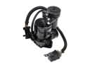 Buick Park Avenue Air Suspension Compressor
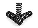 Buick Park Avenue Coil Springs
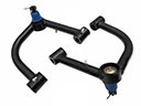 Buick Park Avenue Control Arm
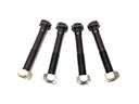 Buick Park Avenue Control Arm Bolt
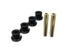 Buick Park Avenue Crossmember Bushing
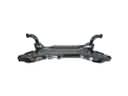 Buick Park Avenue Front Cross-Member
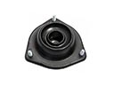 Buick Park Avenue Shock And Strut Mount
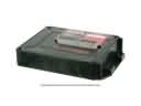 Buick Park Avenue Suspension Control Module
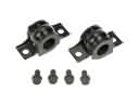 Buick Park Avenue Sway Bar Bracket
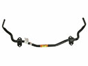 Buick Park Avenue Sway Bar Kit
 Buick Park Avenue Sway Bar Link
 Buick Park Avenue Wheel Hub