ChevyParts
My Garage
My Account
Cart
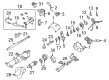
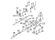
OEM Chevrolet Silverado 1500 Upper Steering Column Bearing
Upper Tilt Steering Column Bearing- Select Vehicle by Model
- Select Vehicle by VIN
Select Vehicle by Model
orMake
Model
Year
Select Vehicle by VIN
For the most accurate results, select vehicle by your VIN (Vehicle Identification Number).
2 Upper Steering Column Bearings found


Chevrolet Silverado 1500 Bearing Assembly Part Number: 88963617
$33.09 MSRP: $54.51You Save: $21.42 (40%)Ships in 1-3 Business Days


Chevrolet Silverado 1500 Shaft Bearings Part Number: 26001827
$50.91 MSRP: $86.67You Save: $35.76 (42%)Ships in 1-3 Business Days
Chevrolet Silverado 1500 Upper Steering Column Bearing
Want to cut long-term maintenance and repair costs? Choose OEM Upper Steering Column Bearing. Those parts deliver top durability you can trust. On our site, you'll find a huge catalog of genuine Chevrolet Silverado 1500 parts. Prices are unbeatable, so you can keep more in your pocket. Every OEM Chevrolet Silverado 1500 Upper Steering Column Bearing includes a manufacturer's warranty. You can also get an easy return policy that keeps buying risk free. Fast delivery, get your car on the road quickly. It's simple to search, compare, and order. Stop guessing about quality or fit. Order today and save with parts that last.
Chevrolet Silverado 1500 Upper Steering Column Bearing Parts Questions & Experts Answers
- Q: How to replace the Upper Steering Column Bearing on Chevrolet Silverado 1500?A:Begin by eliminating the Steering Column followed by removal of the inflatable restraint steering wheel module coil, turn signal multifunction switch, ignition lock cylinder case, tilt spring, automatic transmission control. The compressor (J 23653-SIR) combined with adapter (J 42137) allow removal of Steering Shaft lock plate retaining ring for disposal. Extract the Turn Signal Switch cancel cam position plate together with the Turn Signal Switch cancel cam and Steering Shaft upper bearing spring and Steering Shaft upper bearing inner race seat and Steering Shaft upper bearing inner race from the Steering Column shaft assembly. Use the pivot pin remover (J 21854-01) to remove the two pivot pins which hold the Steering Column tilt head assembly together. Place the tilt lever into the Steering Column tilt head assembly before pulling back the tilt lever while drawing the Steering Column tilt head assembly downward and toward the Steering Column. First separate the Steering Column tilt head assembly from the anti-rotation pin (J 42640), then remove the tilt lever and the Steering Shaft upper bearing from the Steering Column tilt head assembly. Installing the Steering Shaft upper bearing into the Steering Column tilt head assembly precedes Steering Column shaft assembly installation. Move the Steering Column tilt head assembly toward the Steering Column until the steering wheel lock shoes become secured. Install gm p/n 12346293 (Canadian P/N 992723) on pivot pins then push each pin into the Steering Column tilt head assembly while delivering stakes to three points on the Steering Column assembly. The anti-rotation pin (J 42640) with these components must be attached to the Steering Column shaft assembly: do the following steps when installing parts to the Steering Column shaft assembly: apply gm p/n 12345718 (Canadian P/N 10953516) across the Steering Shaft upper bearing inner race then position the Steering Shaft upper bearing inner race and Steering Shaft upper bearing inner race seat and Steering Shaft upper bearing spring followed by gm p/n 12377900 (Canadian P/N 10953529) lubrication of the Turn Signal Switch cancel cam and complete the installation with the Turn Signal Switch cancel cam position plate. The installation process requires use of the compressor j23653-sir and adapter j42137 for the new Steering Shaft lock plate retaining ring followed by automatic transmission control assembly then tilt spring and ignition lock cylinder case and turn signal multifunction switch and inflatable restraint steering wheel module coil until the Steering Column is installed.

Related Chevrolet Silverado 1500 Parts
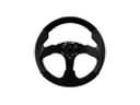 Chevrolet Silverado 1500 Steering Wheel
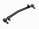 Chevrolet Silverado 1500 Drag Link
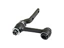 Chevrolet Silverado 1500 Idler Arm
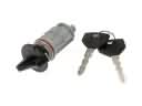 Chevrolet Silverado 1500 Ignition Lock Assembly
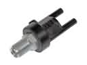 Chevrolet Silverado 1500 Power Steering Control Valve
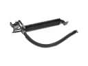 Chevrolet Silverado 1500 Power Steering Cooler
 Chevrolet Silverado 1500 Power Steering Pump
 Chevrolet Silverado 1500 Rack and Pinion Boot
 Chevrolet Silverado 1500 Shift Interlock Solenoid
 Chevrolet Silverado 1500 Steering Column Cover
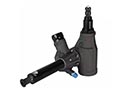 Chevrolet Silverado 1500 Steering Gearbox
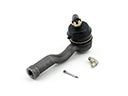 Chevrolet Silverado 1500 Tie Rod End