


Original OEM GM parts deliver superior quality and meet all performance standards needed for optimal automotive operation. The authentic part identified by 26001827 Shaft Bearings is available in the market under the name GM Upper Steering Column Bearing. This genuine product has a full warranty coverage from the manufacturer available at all authorized GM dealers throughout the United States. This part 26001827 Shaft Bearings fits certain Chevrolet S10, Colorado, C10 models, as well as GMC Sierra 1500, Yukon, Canyon. Additionally, it is compatible with Cadillac Escalade, Allante, DTS and Buick Regal, LaCrosse, Lucerne models.
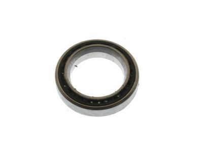
The original GM component designated by manufacturer part number 26001827 maintains top performance when functioning as the Bearing Assembly, Steering Column unit at its Upper. The component 26001827 is constructed from durable material and its dimensions span 1.4 x 1.5 x 0.4 inches while weighing 0.40 Pounds. The Direct Replacement component is ready in New condition to ensure full compatibility with your vehicle system. This component receives the designation of Bearing Assembly; Bearing Kit; Housing Bearing; Upper/Lower Bearings; Steering Column Bearings.. The part 26001827 has available replacement options. GM manufacturer provides a warranty that ensures reliable operation of this product. The Shipping Policy and Return Policy pages outline complete details regarding shipping procedures and return processes.
If you want to save money in the long run on maintenance and repairs, you should choose OEM products because they're of the top level of durability. Are you on the quest of finding GM parts, our site is worth a visit. We stock an endless selection of high-quality GM components including things like ignition coils all the way through to fan shrouds and all at prices that can not be matched. You have nothing to worry about because all our OEM parts are covered with a manufacturer warranty, which guarantees superior quality and value.