
Popular OEM GMC Yukon Parts
- Body & Hardware Parts View More >
- Steering Parts View More >
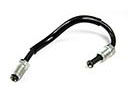
- Electrical Parts View More >
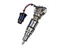
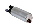
- Air & Fuel Delivery Parts View More >
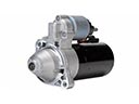
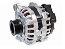
- Charging & Starting Parts View More >
- Engine Parts View More >
- Belts & Cooling Parts View More >
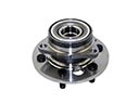
- Suspension Parts View More >
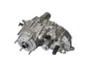
- Driveline & Axles Parts View More >
- Emission Control & Exhaust Parts View More >
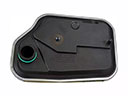
- Transmission Parts View More >
- Brakes Parts View More >


Why Buy Genuine GMC Yukon Parts From ChevyPartsGiant.com
Looking for real GMC Yukon parts? ChevyPartsGiant.com may be a better choice to find genuine parts at wallet-friendly prices. We sell only OEM GMC Yukon parts, ensuring perfect fit, reliability, and long-term performance. With our website, you can easily get access to the same parts found at local GMC stores. All components are produced by GMC and are exclusively fitted on GMC Yukon automobiles. By shopping at our store, you can enjoy the quality of the GMC factory without the high prices of brick-and-mortar facilities. We achieve this because we are an online store operating at lower costs, which we pass on to you. We also have a user-friendly platform where you can find and order genuine GMC Yukon parts swiftly. We are here to make your process of restoring a GMC Yukon or dealing with simple repairs quick and inexpensive. We also make it easy to obtain GMC Yukon parts at competitive shipping prices and a team of knowledgeable staff ready to take your order. Choose ChevyPartsGiant.com to save time and money, as well as keep your GMC Yukon in the good condition.
General Motors produced the GMC Yukon as a full-size SUV after replacing the K5 Jimmy model in 1992. In 1992 General Motors launched the two-door GMC Yukon as their first-generation model following the GMT400 platform with a 111.5-inch wheelbase. The model featured a fuel-efficient 5.7-liter V8 engine as part of its performance engine options. In 2000 the GMT800 platform brought the second generation GMC Yukon to market while its design shifted toward aerodynamics and received a new 6.0-liter V8 engine option. In 2008, a hybrid variant was added to the third-generation Yukon lineup, using GM's 2-Mode Hybrid system to improve fuel efficiency and expand the model's versatility. Under the GMT921/922 platform this generation moved forward with improved driving dynamics together with enhanced handling. In 2013 the fourth generation of the GMC Yukon received an update which implemented the GMT K2XX platform with fold-flat second- and third-row seats to enhance functionality yet reduced available cargo area. GMC Yukon maintains its dedication to manufacturing high-quality products because its official factory produces genuine parts according to the vehicle's engineering standards.
The GMC Yukon vehicles pose three problems, which can be categorized as body hardware and electrical security systems. In body hardware, the power door lock actuator is compromised such that it locks slowly or does not lock at all. Clicks with no latch movement and with intermittent response are related to internal motor damage or gear breakage. A command test, voltage check, and linkage are the diagnosis of each affected door. Repair eliminates the defective power door lock actuator of the GMC Yukon, as well as checks its switch operation. In body hardware, snapping of inside and outside door handles when mounting on the pivot is a possibility. Rigid pulls, slack sensation, or a door that can not be opened indicate failure of the handles. The door handles are replaced to correct the latching on Yukon, and hinge lubrication ensures that less stress is experienced in the future. In electrical anti theft and ignition, the anti theft system can thwart a Yukon start. Worn ignition switch contacts do not provide a flashing security light and do not give a crank. Testing verifies required key recognition, relay commands, and correct voltage at the switch. Repair fits new ignition switch on GMC Yukon, codes cleared, and relearns completed. These measures will reinstate the lock function, handle integrity, and improve reliability on GMC Yukon vehicles.
GMC Yukon Parts and Q&A
- Q: How to replace the alternator on GMC Yukon?A:In order to replace the generator, disconnect the negative battery cable, remove the intake manifold sight shield and accessory drive belt. Unplug the engine harness into the generator and take out the generator. To install, screw the generator, reconnect the battery jumper cable and the engine harness. Lastly, replace the intake manifold sight shield and re-attach negative battery cable.
- Q: How to replace the camshaft on GMC Yukon?A:To change the camshaft, loosen the radiator support and valve lifters and then Timing Chain, Camshaft Position Actuator and Solenoid Valve. The camshaft should be carefully hone out, cleaned and examined. In case of need of replacement, lubricate and refit a camshaft with proper gasket positioning. Then reassemble all the components.
- Q: How to replace the intake manifold with AFM on GMC Yukon?A:In order to install the AFM in place of the intake manifold, the air cleaner outlet duct and generator should be removed. Disassemble different electric connectors and tighten engine harness. Take out intake manifold and gaskets, and block passages on cylinder head. Install the new manifold, connect bolts and reattach elements after which the generator and air cleaner duct should be reinstalled.


