
Popular OEM Chevrolet S10 Parts
- Body & Hardware Parts View More >
- Steering Parts View More >
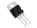
- Electrical Parts View More >
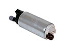
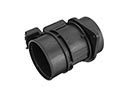
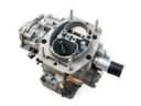
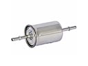
- Air & Fuel Delivery Parts View More >
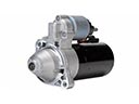
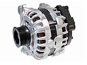
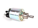
- Charging & Starting Parts View More >
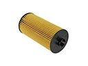
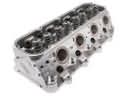
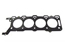
- Engine Parts View More >
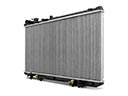
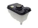
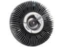
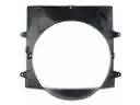
- Belts & Cooling Parts View More >
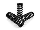
- Suspension Parts View More >
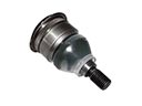
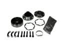
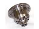
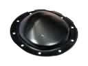
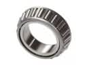
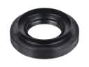
- Driveline & Axles Parts View More >
- Emission Control & Exhaust Parts View More >
- Transmission Parts View More >
- Brakes Parts View More >

Why Buy Genuine Chevrolet S10 Parts From ChevyPartsGiant.com
Looking for real Chevrolet S10 parts? ChevyPartsGiant.com may be a better choice to find genuine parts at wallet-friendly prices. We sell only OEM Chevrolet S10 parts, ensuring perfect fit, reliability, and long-term performance. With our website, you can easily get access to the same parts found at local Chevrolet stores. All components are produced by Chevrolet and are exclusively fitted on Chevrolet S10 automobiles. By shopping at our store, you can enjoy the quality of the Chevrolet factory without the high prices of brick-and-mortar facilities. We achieve this because we are an online store operating at lower costs, which we pass on to you. We also have a user-friendly platform where you can find and order genuine Chevrolet S10 parts swiftly. We are here to make your process of restoring a Chevrolet S10 or dealing with simple repairs quick and inexpensive. We also make it easy to obtain Chevrolet S10 parts at competitive shipping prices and a team of knowledgeable staff ready to take your order. Choose ChevyPartsGiant.com to save time and money, as well as keep your Chevrolet S10 in the good condition.
Since 1982 the Chevrolet S10 has featured numerous engine and transmission combinations to adapt to changing market needs. The initial Chevrolet S10 generation had several engine options starting with the 1.9-liter Isuzu I4 engine and the 2.0-liter GM I4 engine before adding the powerful 4.3-liter LB4 and L35 V6 engines in subsequent years. During the second generation Chevrolet S10 production engineers added two new engine options: the 2.2 L LN2/L43 I4 with the 4.3 L LB4/L35/LF6/LU3 V6 as the other option aiming to boost performance capabilities. The Chevrolet S10 in its third generation included a 2.4 L Flexpower engine producing 147 hp and a 2.8 L Duramax diesel engine to expand user choices for fuel type options. The Chevrolet S10 was available with both a 4-speed automatic transmission and various manual transmission options. Fuel efficiency varied depending on configurations, with gasoline models averaging approximately 17-21 mpg in city driving and 22-28 mpg on highways. The vehicle uses front disc brakes alongside rear drum brakes but includes an optional anti-lock system as a safety feature. The second generation of Chevrolet S10 measures 190 inches long whereas the third generation spans 5235 mm. The market provides authentic Chevrolet S10 parts which exist to fulfill manufacturer specifications to give consumers reliable items for maintenance needs and future enhancements.
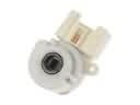
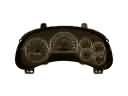
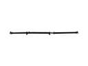
Chevrolet S10 issues group into HVAC cooling, body electrical, and accessory drive. In HVAC, the S10 may leak coolant from the heater core under the right dash. Puddles form on the passenger floor, and engine temperatures rise. Confirm with a pressure test, then replace the heater core and bleed air. Inspections on a Chevrolet S10 should also check hoses and the reservoir level. For the body electrical, the S10 often loses intermittent wiping due to a failed wiper motor circuit board. Symptoms include wipers that stop mid-travel or refuse to start. Inspect the harness grounds, then install a new wiper motor control board. Verify recall coverage with a Chevrolet dealer and test all speeds. In the accessory drive, the S10 can squeal or throw the belt when the serpentine belt tensioner weakens. Look for pulley wobble, dust, and misalignment on the Chevrolet S10. Install an appropriate serpentine belt in place of the tensioner of the serpentine belt. Check after road test the coolant level. These groups have a functional protection of cooling, visibility, and power delivery to the S10. Prioritize leaks first, then wipers, then belt tracking, to preserve Chevrolet reliability.
Chevrolet S10 Parts and Q&A
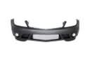
- Q: How to replace the front bumper fascia (Xtreme) on Chevrolet S10?A:In order to remove the front bumper fascia, one has to, first of all, raise the vehicle. Unhook the connector on the foglamp, unscrew the push-pins and screws on the front part of the fascia and dismount it to the impact bar. To install them, screw the fascia and put back the push-pins, re-connect the connector of the foglamp, and lower the vehicle.
- Q: How to replace a water pump on Chevrolet S10?A:To change the cooling system water pump drain, loose the pulley bolts, remove the fan assembly and drive belt. Unscrew the pump water in a pulley and the mounting bolts after which the water pump and gasket are removed. Wipe the surfaces, change gaskets and put back parts, tightening them. Lastly, pour in the radiator and seal the leaks.
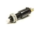
- Q: How to service and repair the starter motor on Chevrolet S10?A:In order to service the starter motor, remove the battery negative cable and lift the vehicle up. If fitted with a differential carrier shield, remove it, and remove the starter mounting bolts and disconnect the wires. Install the starter, shims as required and tighten the mounting bolts. Install the shield when necessary, and close the vehicle and reattach the battery.


