
Popular OEM Chevrolet Silverado 1500 Parts
- Body & Hardware Parts View More >
- Steering Parts View More >
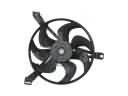
- Electrical Parts View More >
- Air & Fuel Delivery Parts View More >
- Charging & Starting Parts View More >
- Engine Parts View More >
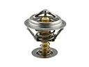
- Belts & Cooling Parts View More >
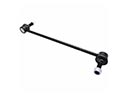
- Suspension Parts View More >
- Driveline & Axles Parts View More >
- Emission Control & Exhaust Parts View More >
- Transmission Parts View More >
- Brakes Parts View More >


Why Buy Genuine Chevrolet Silverado 1500 Parts From ChevyPartsGiant.com
Looking for real Chevrolet Silverado 1500 parts? ChevyPartsGiant.com may be a better choice to find genuine parts at wallet-friendly prices. We sell only OEM Chevrolet Silverado 1500 parts, ensuring perfect fit, reliability, and long-term performance. With our website, you can easily get access to the same parts found at local Chevrolet stores. All components are produced by Chevrolet and are exclusively fitted on Chevrolet Silverado 1500 automobiles. By shopping at our store, you can enjoy the quality of the Chevrolet factory without the high prices of brick-and-mortar facilities. We achieve this because we are an online store operating at lower costs, which we pass on to you. We also have a user-friendly platform where you can find and order genuine Chevrolet Silverado 1500 parts swiftly. We are here to make your process of restoring a Chevrolet Silverado 1500 or dealing with simple repairs quick and inexpensive. We also make it easy to obtain Chevrolet Silverado 1500 parts at competitive shipping prices and a team of knowledgeable staff ready to take your order. Choose ChevyPartsGiant.com to save time and money, as well as keep your Chevrolet Silverado 1500 in the good condition.
The Chevrolet Silverado 1500 entered the market in 1999 to replace the C/K lineup while product designers executed several redesigns to boost its specifications and operating capabilities. At launch in 1999 Chevrolet Silverado 1500 offered three powertrain packages including 200-horsepower 4.3L V6 (Vortec 4300) alongside 275-horsepower 4.8L (Vortec 4800) and 285-horsepower 5.3L (Vortec 5300) engines that came with 325 lb-ft torque. This product launch from Chevrolet in 2007 introduced the GMT900 platform with a 4.3L V6 engine that provided 195 horsepower and 260 lb-ft of torque and operated through four-speed automatic transmission. Between 2013 through 2018 the third generation Chevrolet Silverado 1500 lineup received EcoTec3 engines that brought together these three power options: 4.3L V6 and 5.3L V8 and 6.2L V8 that provided better efficiency resulting in enhanced performance. The third generation Chevrolet Silverado 1500 achieved better handling through its combination of aluminum parts and high-strength steel frames which also brought weight reduction benefits. The transmission technology in Chevrolet Silverado 1500 included an advanced automated six-speed system for logic-based transmissions that enhanced speed and fuel efficiency during gear shifts. Factory-standard parts used in the Chevrolet Silverado 1500 have preserved its excellent manufacturing quality from the start and ensure performance and durable operation for users.
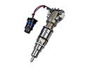
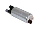
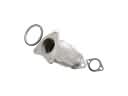
Chevrolet Silverado 1500 issues group into drivetrain control, engine fueling, and fuel level measurement. In drivetrain control, the Silverado 1500 may display a service message and lose mode changes. A failed transfer case position sensor or selector switch confuses the controller. Scan the module, replace the transfer case position sensor, and verify engagement on the Silverado 1500. In engine fueling, the Silverado 1500 can misfire with a warning light. Stuck fuel injector tips starve one bank and cause rough running. Perform cleaning procedures, then replace the fuel injector if flow does not return. In fuel level measurement, the Silverado 1500 may show an erratic gauge. A worn fuel level sensor inside the module causes false readings on the Silverado 1500. Replace the fuel pump module on high mileage trucks and inspect connectors. Follow Chevrolet electrical tests to confirm power and grounds. Apply Chevrolet torque specs and sealing checks during reassembly. Complete a road test and relearn drive cycles using Chevrolet procedures. Record pressures and trims so the Silverado 1500 remains predictable. Verify no leaks and confirm stable temperatures after service on the truck. These steps organize faults by system and restore dependable operation.
Chevrolet Silverado 1500 Parts Questions & Answers
- Q: How to replace the distributor on Chevrolet Silverado 1500?A:To replace the Distributor, the air cleaner outlet resonator needs to be removed and the cold electrical connectors from the straight propulsion (CMP) sensor and the gas/oil pressure sensor need to be disconnected. Then, take off the Ignition Coil wire from the coil and from the Distributor Cap, then the Spark Plug Wires by twisting each boot 1/2 turn and pull the wire boot. Screw out the Distributor Cap and take it off. Mark the position of the rotor in relation to the housing of the Distributor as well as Intake Manifold and pull out the Distributor hold down bolt then distrubutor thus observing that the rotor will move clock wise 42 degrees. When installing, use a second mark on the base of the Distributor for alignment. If a new Distributor needs to be installed, there must be two marks on the housing and they must be placed in the same location as the old one; rotor must be aligned with the second mark and the Distributor is to be installed in such a way that the rotor turns clockwise about 42 degrees. The rotor division should end on the mark on the Distributor base ; if it doesn't, the Distributor should be removed and replaced. Torque the Distributor hold down bolt to 25 n.m (18 lb ft), install the cap to the Distributor with new screws torqued to 2.4 n.m (21 lb in) and re-attach the cmp sensor and fuel pump/oil pressure sensor. Reattach the Ignition Coil wire by placing the coil wire nipple in an angle of 35 to 60 degrees aft of perpendicular from the engine centerline. If the malfunction indicator lamp (MIL) is on and dtc p1345, dist. Will be installed improperly. For the second installation, rotate the number 1 cylinder to top dead center (TDC) of the compression stroke, matching the crankshaft balancer marks with the engine front cover tabs. Line up the white paint mark on the Distributor stem with the pre-drilled indent hole in the gear to align the rotor segment with a v6 engine . Position the oil pump drive shaft with that of the Distributor drive tab using a long screwdriver and insert the Distributor into the engine with the spark plug towers parallel to the engine centerline, and the rotor segment parallel to this on the Distributor base. Hold down bolt on the Distributor to the front to 25 n.m (18 lb ft); install the Distributor Cap with new screws going to 2.4 n.m (21 lb in) and connect the cmp sensor and fuel pump/oil pressure sensor and reconnect the Ignition Coil wire in return going with the right orientation. In case the mil is on following the installation, please repeat the second installation procedure; in case it is not, install the air cleaner outlet resonator.
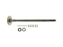
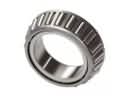
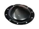
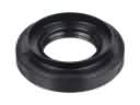
- Q: What tools are required to service and repair the rear axle wheel bearing and wheel seal on Chevrolet Silverado 1500?A:A set of essential tools consisting of j 8092 universal driver handle (J 8092), j 21128 axle pinion oil seal installer (J 21128), j 23690 bearing installer (J 23690), j 2619-01 slide hammer (J 2619-01), j 45857 tone wheel or bearing remover (J 45857) is needed for servicing and repairing the rear Axle Shaft seal or bearing. The following tools must be used for rear Axle Shaft seal and bearing service: j 8092 universal driver handle (J 8092), j 21128 axle pinion oil seal installer (J 21128), j 23690 bearing installer (J 23690), j 2619-01 slide hammer (J 2619-01), and j 45857 tone wheel or bearing remover (J 45857). Begin service by both elevating the vehicle and removing tire wheels. Begin by removing two components from the rear axle housing: rear axle housing cover and Axle Shaft. When working with the seal only it requires an appropriate seal removal tool. Use j 45857 and j 2619-01 to extract the Axle Shaft seal and bearing simultaneously from the housing. Two installation tools are required: j 23690 and j 8092 . Insert the Axle Shaft bearing into the housing by applying force to the tool until it stops at the tube's surface. Use the j 21128 tool to drive the seal into the bore until it reaches tube surface level. The installation process includes placing the Axle Shaft followed by reinstalling the rear axle housing cover and the tire and wheel assembly. After filling the rear axle with lubricant the vehicle should be lowered into place.
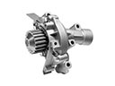
- Q: How to replace the water pump on a 4.3L engine on Chevrolet Silverado 1500?A:A 4.3l engine Water Pump requires the use of j 41240 fan clutch remover and installer for replacement. First remove the air cleaner outlet clamp above the sensor before disconnecting the pcv hose and air cleaner adapter nut. Shift the outlet duct of the air cleaner upward to detach its connection to the Throttle Body. Remove all cooling fluid from the engine and disconnect both accessory components which are the cooling fan and Drive Belt. After moving the radiator outlet hose clamps away from the surge tank and Water Pump you can detach it from both components. Turn and loosen the Water Pump inlet hose clamps for install. After that take out the inlet hose. Secure the Water Pump Pulley with the fan clutch remover and installer (J 41240) and proceed by taking off the pulley bolts followed by the Water Pump bolts to remove the Water Pump. Take out the damaged gaskets from the Water Pump and inspect the pump parts for damage. Use gm p/n 12346004 material (Canadian P/N 10953480) as sealant when reusing old Water Pump bolts. The technician should place new gaskets on top of the Water Pump and put the Water Pump into place before tightening all bolts to 45nm (33 ft. Lbs.). Adopt the fan clutch remover and installer j 41240 to support the Water Pump Pulley during bolt installation at 25 nm (18 ft. Lbs.). Keep the hose clamp tangs facing forward from the Water Pump toward the inlet hose then position the clamp upper tang for matching with the hose outer diameter. Install the inlet hose and set its clamps. After placing radiator outlet hoses on the Water Pump and surge tank you should relocate their clamps into position. Fasten the cooling fan and Drive Belt while inserting the hinge clip into its lip on the Throttle Body to fit the air cleaner outlet duct. Rotate the duct downward until the mounting stud enters its hole. Fasten the air cleaner adapter nut and pcv hose while tightening the air cleaner outlet duct clamp at the maf/iat sensor to 4 nm (35 inch lbs.). Complete filling the cooling system and check for any fluid leaks.
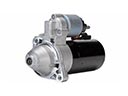
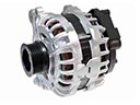
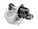
- Q: How to replace an alternator on Chevrolet Silverado 1500?A:A battery negative cable disconnect and Drive Belt removal stands as the first step when changing the generator. Remove the generator cable from its electrical connector while sliding the boot down to expose the terminal stud before removing the generator cable nut from the stud. The generator bolts need removal before extracting the generator unit from its place. The installation process begins by putting the generator where it should go then tightening generator bolts to 50 n.m (37 lb ft). For generator cable attachment install the cable then secure it with the generator cable nut until torque reaches 9 n.m (80 lb in) and slide the boot over the terminal stud. The generator electrical connector should be connected firstly followed by Drive Belt installation and lastly negative Battery Cable reconnection.


