Make sure this part fits

GM 26050549
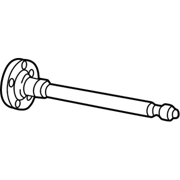
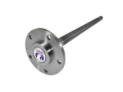
Axle Shaft, Rear

1995-2005 GM

Customer Questions & Expert Answers (11)
GM 26050549 Axle Shaft, Rear
  • Part Description
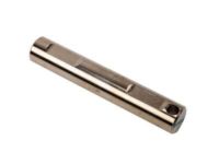
    Shaft, Rear Axle Drive
  • Position
    Rear
  • Manufacturer
    General Motors
  • Manufacturer's Notes
    This part is discontinued.
Make sure this part fits
  • Related Parts
  • Product Specifications
  • Vehicle Fitment
  • Customer Questions & Expert Answers
  • Product Specifications

    BrandGenuine GM
    Manufacturer Part Number26050549
    Part DescriptionShaft, Rear Axle Drive
    Other NamesAxle Shafts
    Item Dimensions33.1 x 6.8 x 6.6 inches
    Item Weight15.70 Pounds
    PositionRear
    ConditionNew
    Fitment TypeDirect Replacement
    Require Quantity2
    ManufacturerGeneral Motors
    SKU26050549
    WarrantyThis genuine GM part is guaranteed by GM's factory warranty.
    Shipping & ReturnShipping Policy Return Policy
    Warning: California's Proposition 65
  • Vehicle Fitment

    Year Make Model Trim Engine
    1995-2005 Chevrolet BlazerBase, LS, LT, Trailblazer, Xtreme, ZR26 Cyl 4.3 L GAS
    1998-2004 Chevrolet S10Base, LS, SS, Xtreme, ZR2, ZR54 Cyl 2.2 L FLEX, 4 Cyl 2.2 L GAS, 6 Cyl 4.3 L GAS
    1995-2001 GMC JimmyBase, Diamond Edition, Envoy, SL, SLE, SLS, SLT6 Cyl 4.3 L GAS
    1998-2004 GMC SonomaSL, SLE, SLS4 Cyl 2.2 L FLEX, 4 Cyl 2.2 L GAS, 6 Cyl 4.3 L GAS
    1996-2004 Oldsmobile BravadaBase6 Cyl 4.2 L GAS, 6 Cyl 4.3 L GAS
  • Customer Questions & Expert Answers

    Q:
    Can you help me check if this 26050549 is the right part for my car? Posted by ChevyPartsGiant Specialist
    A:
    Please Select Your Vehicle model to see if part number 26050549 is suitable before ordering.
    Posted by ChevyPartsGiant Specialist
    Q:
    How to replace the wheel axle shaft on Chevrolet Blazer? Posted by Customer
    A:
    The replacement process for an Axle Shaft begins by unlocking the Steering Column for steering linkage mobility followed by construction of the vehicle and applying suitable safety stands for stabilization. Insert a drift through the brake caliper into one of the rotor vanes before handling the two front tire and wheel assemblies and drive axle which needs to be prevented from turning. After taking out the drift from the brake rotor users should remove the axle nut along with its washer. The caliper should be suspended with wire while you remove its front rotors to prevent brake hose damage. The upper Control Arm needs its abs wire and brake hose brackets detached before removing the abs bracket from the Ball Joint of the upper Control Arm. Secure the frame to the hoist while preventing it from moving so the safety stand avoids damage to any system components. A safety stand should be positioned beneath the lower Control Arm for proper support of the Steering Knuckle assembly together with the lower Control Arm using another safety stand. Strike the axle outer end with a brass drift to detach the Axle Shaft through hammering. The Steering Knuckle assembly needs wire support to protect the outer tie rod and abs wire before workers can remove both the upper Ball Joint and lower shock absorber part. Push the differential carrier-end of the Axle Shaft toward the carrier to generate enough space for removing the knuckle assembly after you loosen the lower Ball Joint from the knuckle. Lower the safety stand from the lower Control Arm until Torsion Bar pressure decreases because clearance needs to expand without harming the axle seal. Proceed by removing the lower Ball Joint followed by the axle from the Steering Knuckle assembly. To disconnect the left and right side axle shafts from the differential carrier strike a piece of wooden or brass drift against the tripot housing until snap ring pressure is overcome. Then remove the front differential carrier shield. Begin the differential carrier axle removal by extracting it straight forward while your support keeps the boot from tearing. The operation of a vehicle becomes unsafe when the driver operates it without front axle nuts or shafts. Also the vehicle weight should never load the front wheels through its weight. Finally, remove the axle. A shop towel must cover all sharp edges on the shock mounting bracket and lower Control Arm ball stud to shield the boot from damage during installation. Install the Axle Shaft to the differential carrier through spline alignment while guiding the axle into the differential carrier seal and then drive the shaft straight until the snap ring seats. Enter the safety stand underneath the lower Control Arm weight before you begin slowly placing the knuckle onto the axle while putting the ball stud into the correct spot on the Steering Knuckle. The installation order includes lower Ball Joint and lower shock absorber section and the upper Ball Joint assembly. Begin by putting the axle washer and nut along with its proper torque of 140 nm (103 ft. Lbs.). Then install the abs bracket that sits on the upper Control Arm Ball Joint as well as components which hold the abs wire and brake hose will follow. First install the front brake rotors with the front differential carrier shield after removing the frame strap to install both front tire and wheel assemblies when the vehicle reaches the ground level.
    Posted by ChevyPartsGiant Specialist
    Q:
    How to replace the rear axle shaft on GMC Jimmy? Posted by Customer
    A:
    Vehicle Axle Shaft replacement begins with vehicle lift and tire removal before proceeding to brake caliper and Brake Drum removal when applicable. Begin by removing the pinion shaft locking bolt after you take off both the rear cover and its installed gasket. When maintaining axles which lack locking differentials users need to remove their pinion shafts first. When dealing with a locking Differential system begin by pulling the shaft halfway out before rotating the case to enable pinion shaft contact with the housing. Push a screwdriver-like tool into the lock to rotate it until it lines up perfectly with the thrust block. To detach the c-lock from the Axle Shaft end push its flange toward the Differential direction. The Axle Shaft must not be rotated during removal because it leads to gear misalignment which creates difficulties during reassembly. Insert the new Axle Shaft into its housing slot while making sure the Differential side gear accepts its splines. When dealing with wheel shafts without Differential lock you need to activate the locking mechanism at the shaft's button end. When you have a locking Differential keep your pinion shaft partially extended and position the c-lock directly on the Axle Shaft with both ends facing the thrust block. Pull the shaft flange outward to position the lock inside the Differential gear while the pinion shaft hole centers with the Differential case bolt hole. The new pinion shaft locking bolt requires a torque setting of 36 nm (27 ft. Lbs.) for installation. After reinstalling the brake caliper and Brake Drum if present use the rear cover and gasket before reassembling the tire and wheel assembly. Place the correct fluid into the rear axle before lowering the vehicle.
    Posted by ChevyPartsGiant Specialist
    Q:
    How to replace the rear axle shaft on Chevrolet S10? Posted by Customer
    A:
    The vehicle should be raised before starting to replace rear axle shafts while you also remove tire and wheel assemblies. If your vehicle has these components you need to remove its brake caliper and Brake Drum. The next action involves removing both the rear cover and gasket before removing the pinion shaft locking bolt. Owners of axles without locking differentials should take off the pinion shaft first. Those with locking differentials should first remove the shaft's middle section before slowly rotating the case until the pinion shaft reaches the housing. A screwdriver-type tool helps you to turn the Differential case lock until it points directly at the thrust block. Use a tool to push the Axle Shaft flange toward the Differential after removing its c-lock from the button end. Important: avoid Axle Shaft rotation when removing it because this action might cause gear misalignment that makes reassembly more complicated. Extract the housing's Axle Shaft. During installation, manually position the Axle Shaft inside the rear axle housing so the splines can align with the Differential side gear. If your axle does not have a locking Differential then apply the lock on the button end of the Axle Shaft. C-lock users maintaining a partial position of the pinion shaft should align its ends with the thrust block while installing the c-lock on the Axle Shaft. Pull the shaft flange away from your body until the lock enters the Differential gear while aligning the pinion shaft's hole with the Differential case's screw hole. Thread the new pinion shaft locking bolt into position and torque it to 36 nm (27 ft. Lbs.). Put the brake caliper (if present) back first along with the gasket and rear cover and Brake Drum (if installed). Then return the tire-wheel assembly to its position. The correct fluid needs to be added to the rear axle portion before the vehicle reaches the floor.
    Posted by ChevyPartsGiant Specialist
    Q:
    How to replace the wheel axle shaft on GMC Sonoma? Posted by Customer
    A:
    The replacement process for an Axle Shaft begins by unlocking the Steering Column for steering linkage mobility followed by construction of the vehicle and applying suitable safety stands for stabilization. Insert a drift through the brake caliper into one of the rotor vanes before handling the two front tire and wheel assemblies and drive axle which needs to be prevented from turning. After taking out the drift from the brake rotor users should remove the axle nut along with its washer. The caliper should be suspended with wire while you remove its front rotors to prevent brake hose damage. The upper Control Arm needs its abs wire and brake hose brackets detached before removing the abs bracket from the Ball Joint of the upper Control Arm. Secure the frame to the hoist while preventing it from moving so the safety stand avoids damage to any system components. A safety stand should be positioned beneath the lower Control Arm for proper support of the Steering Knuckle assembly together with the lower Control Arm using another safety stand. Strike the axle outer end with a brass drift to detach the Axle Shaft through hammering. The Steering Knuckle assembly needs wire support to protect the outer tie rod and abs wire before workers can remove both the upper Ball Joint and lower shock absorber part. Push the differential carrier-end of the Axle Shaft toward the carrier to generate enough space for removing the knuckle assembly after you loosen the lower Ball Joint from the knuckle. Lower the safety stand from the lower Control Arm until Torsion Bar pressure decreases because clearance needs to expand without harming the axle seal. Proceed by removing the lower Ball Joint followed by the axle from the Steering Knuckle assembly. To disconnect the left and right side axle shafts from the differential carrier strike a piece of wooden or brass drift against the tripot housing until snap ring pressure is overcome. Then remove the front differential carrier shield. Begin the differential carrier axle removal by extracting it straight forward while your support keeps the boot from tearing. The operation of a vehicle becomes unsafe when the driver operates it without front axle nuts or shafts. Also the vehicle weight should never load the front wheels through its weight. Finally, remove the axle. A shop towel must cover all sharp edges on the shock mounting bracket and lower Control Arm ball stud to shield the boot from damage during installation. Install the Axle Shaft to the differential carrier through spline alignment while guiding the axle into the differential carrier seal and then drive the shaft straight until the snap ring seats. Enter the safety stand underneath the lower Control Arm weight before you begin slowly placing the knuckle onto the axle while putting the ball stud into the correct spot on the Steering Knuckle. The installation order includes lower Ball Joint and lower shock absorber section and the upper Ball Joint assembly. Begin by putting the axle washer and nut along with its proper torque of 140 nm (103 ft. Lbs.). Then install the abs bracket that sits on the upper Control Arm Ball Joint as well as components which hold the abs wire and brake hose will follow. First install the front brake rotors with the front differential carrier shield after removing the frame strap to install both front tire and wheel assemblies when the vehicle reaches the ground level.
    Posted by ChevyPartsGiant Specialist
    Q:
    What should be done to prevent boot damage during installation for the 2005 Chevrolet Blazer? Posted by Customer
    A:
    Cover the shock mounting bracket, lower control arm ball stud, and any sharp edges with a shop towel.
    Posted by ChevyPartsGiant Specialist
    See expert answers on similar Axle Shaft
    Q:
    What should be done after unlocking the steering column for the 2002 Chevrolet S10? Posted by Customer
    A:
    Raise the vehicle and support it with suitable safety stands.
    Posted by ChevyPartsGiant Specialist
    See expert answers on similar Axle Shaft
    Q:
    How do you remove the inner axle shaft and housing assembly for the 2003 Chevrolet S10? Posted by Customer
    A:
    Carefully work the inner axle shaft and housing assembly out of the drive axle.
    Posted by ChevyPartsGiant Specialist
    See expert answers on similar Axle Shaft
    Q:
    How do you handle the pinion shaft for axles without a locking differential for the 2003 Chevrolet S10? Posted by Customer
    A:
    Remove the pinion shaft.
    Posted by ChevyPartsGiant Specialist
    See expert answers on similar Axle Shaft
    Q:
    What should be done after installing the new inner axle shaft bearing and seal for the 2001 GMC Jimmy? Posted by Customer
    A:
    Insert the inner axle shaft into the housing and place the thrust washer, ensuring the tabs align with the slot in the housing.
    Posted by ChevyPartsGiant Specialist
    See expert answers on similar Axle Shaft
    Q:
    What is the next step after removing the brake components for the 2000 GMC Jimmy? Posted by Customer
    A:
    Take off the axle housing cover and remove the pinion shaft lock bolt and the pinion shaft.
    Posted by ChevyPartsGiant Specialist
    See expert answers on similar Axle Shaft
    If you have any questions about this product, please don't hesitate to ask us. We will be happy to help you!

OEM GM 26050549, Excellent Performance and Perfect Fitment

To ensure reliability, purchase GM part # 26050549 Axle Shaft, Rear. It is sometimes referred to as GM Axle Shaft. Choosing OEM parts is the optimal decision for guaranteeing superior quality and perfect performance. These components undergo stringent quality checks and are carefully constructed to comply with GM's factory specifications, ensuring a smooth installation process.

ChevyPartsGiant.com is a leading supplier of genuine GM parts such as GM 26050549 Axle Shaft, Rear. Our website boasts an extensive inventory of OEM GM parts, available at highly competitive prices in the market. Should you require any new genuine GM parts, rest assured we will deliver them swiftly and efficiently to your doorstep. Furthermore, all our parts come with the assurance of a manufacturer's warranty. For detailed Chevy parts information, click here.
Choose ChevyPartsGiant for discounted prices, exceptional service and fast delivery