ChevyParts
My Garage
My Account
Cart
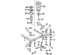
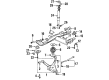
OEM 2001 Cadillac DeVille Control Arm
Suspension Arm- Select Vehicle by Model
- Select Vehicle by VIN
Select Vehicle by Model
orMake
Model
Year
Select Vehicle by VIN
For the most accurate results, select vehicle by your VIN (Vehicle Identification Number).
4 Control Arms found


2001 Cadillac DeVille Control Arm, Driver Side Part Number: 25766511
$195.81 MSRP: $317.79You Save: $121.98 (39%)Product Specifications- Other Name: Arm, Steering Knuckle Upper & Lower Control; Suspension Control Arm and Ball Joint Assembly; Control Arm Assembly; Lower Control Arm; Arm, Steering Knuckle Lower Control
- Position: Driver Side
- Replaces: 25699467, 25703055, 25672870, 25696334, 88967801, 25766508, 25746324, 88986632, 25702221, 25745395
- Item Weight: 8.50 Pounds
- Item Dimensions: 18.8 x 16.1 x 4.4 inches
- Condition: New
- Fitment Type: Direct Replacement
- SKU: 25766511
- Warranty: This genuine part is guaranteed by GM's factory warranty.

2001 Cadillac DeVille Control Arm, Passenger Side Part Number: 25766510
$195.81 MSRP: $317.79You Save: $121.98 (39%)Product Specifications- Other Name: Arm, Steering Knuckle Upper & Lower Control; Suspension Control Arm and Ball Joint Assembly; Control Arm Assembly; Lower Control Arm; Arm, Steering Knuckle Lower Control
- Position: Passenger Side
- Replaces: 19202594, 25696335, 25766509, 25672871, 88986633, 25746325, 25702222, 25703056, 25699468
- Item Weight: 8.40 Pounds
- Item Dimensions: 19.3 x 16.2 x 4.3 inches
- Condition: New
- Fitment Type: Direct Replacement
- SKU: 25766510
- Warranty: This genuine part is guaranteed by GM's factory warranty.


 Product Specifications
- Other Name: Arm Assembly-Rear Suspension Control; Lower Control Arm; Arm, Rear Axle Control Arm
- Position: Rear Passenger Side
- Replaces: 15897790, 25771881
- Item Weight: 17.30 Pounds
- Item Dimensions: 28.4 x 21.7 x 7.7 inches
- Condition: New
- Fitment Type: Direct Replacement
- SKU: 25820033
- Warranty: This genuine part is guaranteed by GM's factory warranty.


 Product Specifications
- Other Name: Arm Assembly-Rear Suspension Control; Lower Control Arm; Arm, Rear Axle Control Arm
- Position: Rear Driver Side
- Replaces: 15897788, 25626733, 25743300, 25675172, 25690655, 25765590, 25699091, 25628897
- Item Weight: 16.80 Pounds
- Item Dimensions: 31.2 x 22.1 x 8.2 inches
- Condition: New
- Fitment Type: Direct Replacement
- SKU: 25820031
- Warranty: This genuine part is guaranteed by GM's factory warranty.
2001 Cadillac DeVille Control Arm
With a comprehensive array of OEM 2001 Cadillac DeVille Control Arm, from fuel pumps to door handles, our website is a one-stop-shop for your needs. All our genuine 2001 Cadillac DeVille Control Arm are backed by the manufacturer's warranty and are offered at competitive prices in the market. Rest assured, you can shop with complete confidence.
2001 Cadillac DeVille Control Arm Parts and Q&A
- Q: How to replace the lower control arm (FE7) on 2001 Cadillac DeVille?A: The lower Control Arm (FE7) requires a two-step replacement process which begins with vehicle elevation and frame-supported suspension for arm free mobility. First eliminate the wheel and tire followed by separation of the stabilizer link bolt from the Control Arm. Cotter pins and hex nuts need to be removed from the ball joint studs. You need to employ the ball joint separator (J 39549) to split the ball joint from the lower Control Arm while also taking out your Control Arm by removing its mounting nuts and bolts. Begin Control Arm installation by setting the arm into its position on the frame while leaving Control Arm nuts loose until achieving design trim height while supporting vehicle weight with control arms then tightening mounting nuts. Begin installation by attaching the stabilizer link to the Control Arm before installing Control Arm bolts together with washers and nuts. Place the ball joint stud into the lower Control Arm before threading on the ball joint nut. Tighten the stabilizer shaft link assembly nut to 23 nm (17 ft. Lbs.) along with the ball joint stud nut to 30 nm (22 inch lbs.) before performing an extra 190-degree rotation. Congratulations, you finished the procedure successfully by inserting a cotter pin before you return the tire and wheel into place while torquing wheel nuts to 125 nm (80 ft. Lbs.). Jounce the vehicle after lowering it then apply torque of 162 nm (120 ft. Lbs.) to nuts for front lower control arms and 146 nm (108 ft. Lbs.) to rear lower Control Arm nuts.
Related 2001 Cadillac DeVille Parts
 2001 Cadillac DeVille Axle Beam Mount
 2001 Cadillac DeVille Coil Spring Insulator
 2001 Cadillac DeVille Coil Springs
 2001 Cadillac DeVille Control Arm Bracket
 2001 Cadillac DeVille Crossmember Bushing
 2001 Cadillac DeVille Shock Absorber
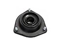 2001 Cadillac DeVille Shock And Strut Mount
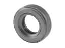 2001 Cadillac DeVille Strut Bearing
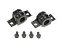 2001 Cadillac DeVille Sway Bar Bracket
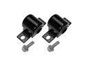 2001 Cadillac DeVille Sway Bar Bushing
 2001 Cadillac DeVille Sway Bar Kit
 2001 Cadillac DeVille Wheel Hub