ChevyParts
My Garage
My Account
Cart
OEM 2001 Cadillac Seville Rack And Pinion
Steering Rack And Pinion- Select Vehicle by Model
- Select Vehicle by VIN
Select Vehicle by Model
orMake
Model
Year
Select Vehicle by VIN
For the most accurate results, select vehicle by your VIN (Vehicle Identification Number).
1 Rack And Pinion found


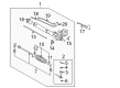
2001 Cadillac Seville Steering Gear Part Number: 19330448
Product Specifications- Other Name: Gear Kit, Steering (Remanufacture); Gear Assembly; Steering Gear Assembly; Gear Kit, Steering
- Replaces: 19169230, 26098942, 26067451, 26088606, 26099972
- Item Weight: 22.60 Pounds
- Item Dimensions: 51.5 x 11.1 x 6.1 inches
- Condition: New
- Fitment Type: Direct Replacement
- SKU: 19330448
- Warranty: This genuine part is guaranteed by GM's factory warranty.
2001 Cadillac Seville Rack And Pinion
With a comprehensive array of OEM 2001 Cadillac Seville Rack And Pinion, from fuel pumps to door handles, our website is a one-stop-shop for your needs. All our genuine 2001 Cadillac Seville Rack And Pinion are backed by the manufacturer's warranty and are offered at competitive prices in the market. Rest assured, you can shop with complete confidence.
2001 Cadillac Seville Rack And Pinion Parts and Q&A
- Q: How to service and repair the Rack and Pinion steering gear for a right-hand drive on 2001 Cadillac Seville?A: When servicing or repairing the Rack And Pinion in right-hand drive vehicles keep both wheels aligned and ensure that the Steering Column remains locked to protect the coil assembly. J 42640 must be installed into the lower Steering Column trim cover access hole to secure the column. After raising and supporting the vehicle proceed by removing the tires along with the wheels. First drain the outer tie rod ends retaining nuts using j 24319-b to detach the outer tie rod ends from the Steering Knuckle. Disengage the cvrss link from the control arms followed by removing the power steering Rack And Pinion heat shield. Extract the power steering Rack And Pinion through disconnection of the intermediate shaft that comes loose after removing the lower pinch bolt. The installation requires disconnecting the variable effort steering electrical connector when this component is present. First remove the rear transmission mount upper mounting nuts and then disconnect the brake line brackets from the engine frame. A drain pan should be placed under the vehicle before technicians remove the power steering pressure and return hose from the power steering Rack And Pinion and finally remove the power steering Rack And Pinion mounting bolts. Prior to lowering the frame partially a supporting system should be implemented because this prevents unnecessary damage. Position the rear of the engine frame 101 mm (4 inches) lower then remove mounting bolts from the upper transmission mount bracket and transmission mount bracket. The power steering Rack And Pinion requires extraction through the lh wheelwell after removing the lh stabilizer shaft insulator. Reposition the power steering Rack And Pinion by way of the left-hand wheelwell to install it back inside the vehicle along with installing the lh stabilizer shaft insulator. Liberate the upper transmission mount bracket while fixing it with bolts at 50 nm (37 ft. Lbs.). Use an engine hoist to lift the rear section of the engine frame before you start installing engine frame rear mounting bolts and torque them to 192 nm (142 ft. Lbs.). Next remove the engine frame support then install the power steering Rack And Pinion mounting bolts. The power steering pressure and return hoses must be remounted to the power steering Rack And Pinion using a torque of 27 nm (20 ft. Lbs.). Connect the brake line brackets to the engine frame before installing the rear transmission mount upper mounting nuts. Tighten all the nuts to 75 nm (55 ft. Lbs.). After connecting the variable effort steering electrical connector, install the intermediate shaft onto the power steering Rack And Pinion followed by lower pinch bolt tightening to 45 nm (33 ft. Lbs.). Place the power steering Rack And Pinion heat shield back in position while connecting the cvrss link to lower control arms and tightening the outer tie rod ends retaining nuts to 47 nm (35 ft. Lbs.). After installing the Steering Knuckle's outer tie rod ends, place tires and wheels back on before lowering the vehicle. You should conclude with the removal of j 42640 from the lower Steering Column trim cover access hole followed by power steering system bleeding and front toe adjustment.
Related 2001 Cadillac Seville Parts
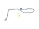 2001 Cadillac Seville Power Steering Hose
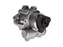 2001 Cadillac Seville Power Steering Pump
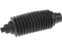 2001 Cadillac Seville Rack and Pinion Boot
 2001 Cadillac Seville Radius Heat Shield
 2001 Cadillac Seville Steering Angle Sensor
 2001 Cadillac Seville Steering Column
 2001 Cadillac Seville Steering Column Seal
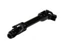 2001 Cadillac Seville Steering Shaft
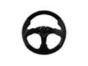 2001 Cadillac Seville Steering Wheel
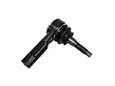 2001 Cadillac Seville Tie Rod
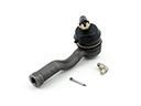 2001 Cadillac Seville Tie Rod End
 2001 Cadillac Seville Upper Steering Column Bearing