ChevyParts
My Garage
My Account
Cart
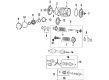
OEM 2004 Chevrolet Corvette Drive Shaft
Axle Shaft- Select Vehicle by Model
- Select Vehicle by VIN
Select Vehicle by Model
orMake
Model
Year
Select Vehicle by VIN
For the most accurate results, select vehicle by your VIN (Vehicle Identification Number).
2 Drive Shafts found

2004 Chevrolet Corvette Drive Shaft Part Number: 88894025
Product Specifications- Other Name: Shaft Assembly, Propeller; Driveshaft; Shaft, Propeller
- Item Weight: 23.50 Pounds
- Item Dimensions: 64.3 x 8.7 x 8.2 inches
- Condition: New
- Fitment Type: Direct Replacement
- SKU: 88894025
- Warranty: This genuine part is guaranteed by GM's factory warranty.

2004 Chevrolet Corvette Drive Shaft Part Number: 88894016
Product Specifications- Other Name: Shaft; Driveshaft; Shaft, Propeller
- Condition: New
- Fitment Type: Direct Replacement
- SKU: 88894016
- Warranty: This genuine part is guaranteed by GM's factory warranty.
2004 Chevrolet Corvette Drive Shaft
With a comprehensive array of OEM 2004 Chevrolet Corvette Drive Shaft, from fuel pumps to door handles, our website is a one-stop-shop for your needs. All our genuine 2004 Chevrolet Corvette Drive Shaft are backed by the manufacturer's warranty and are offered at competitive prices in the market. Rest assured, you can shop with complete confidence.
2004 Chevrolet Corvette Drive Shaft Parts and Q&A
- Q: What Tools Are Required to Service and Repair the Drive Shaft of an Automatic Transmission on 2004 Chevrolet Corvette?A: In order to service and repair the drive/propeller shaft of an automatic transmission, collect tools needed and disconnect negative battery cable. Lift the car, undo parts, and hold together parts. Loose wiring and lower the drive line, making sure that there are no connections. Install parts, re-connect wiring, and restart the engine to test.
Related 2004 Chevrolet Corvette Parts
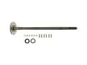 2004 Chevrolet Corvette Axle Shaft
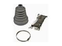 2004 Chevrolet Corvette CV Boot
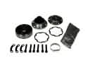 2004 Chevrolet Corvette CV Joint
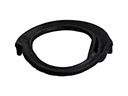 2004 Chevrolet Corvette Coil Spring Insulator
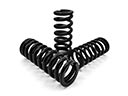 2004 Chevrolet Corvette Coil Springs
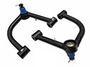 2004 Chevrolet Corvette Control Arm
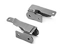 2004 Chevrolet Corvette Control Arm Bracket
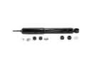 2004 Chevrolet Corvette Shock Absorber
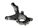 2004 Chevrolet Corvette Steering Knuckle
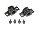 2004 Chevrolet Corvette Sway Bar Bracket
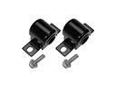 2004 Chevrolet Corvette Sway Bar Bushing
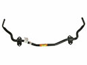 2004 Chevrolet Corvette Sway Bar Kit