ChevyParts
My Garage
My Account
Cart
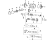
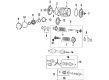
OEM Chevrolet Corvette Drive Shaft
Axle Shaft- Select Vehicle by Model
- Select Vehicle by VIN
Select Vehicle by Model
orMake
Model
Year
Select Vehicle by VIN
For the most accurate results, select vehicle by your VIN (Vehicle Identification Number).
10 Drive Shafts found


Chevrolet Corvette Drive Shaft Part Number: 23357418
$1745.92 MSRP: $2746.21You Save: $1000.29 (37%)Ships in 1-3 Business Days
Chevrolet Corvette Drive Shaft Part Number: 23366290
$1040.29 MSRP: $1328.04You Save: $287.75 (22%)Ships in 1-3 Business Days

Chevrolet Corvette Drive Shaft Part Number: 89059715
$950.20 MSRP: $1222.90You Save: $272.70 (23%)
Chevrolet Corvette Drive Shaft Part Number: 23366291
$839.83 MSRP: $1314.10You Save: $474.27 (37%)Ships in 1-3 Business Days
Chevrolet Corvette Drive Shaft Part Number: 89059712
$971.11 MSRP: $1534.85You Save: $563.74 (37%)Ships in 1-3 Business DaysChevrolet Corvette Drive Shaft Part Number: 89060059

Chevrolet Corvette Drive Shaft Part Number: 12456226

Chevrolet Corvette Drive Shaft Part Number: 88894025
Chevrolet Corvette Drive Shaft Part Number: 88894016
Chevrolet Corvette Drive Shaft Part Number: 12456207
Chevrolet Corvette Drive Shaft
Want to cut long-term maintenance and repair costs? Choose OEM Drive Shaft. Those parts deliver top durability you can trust. On our site, you'll find a huge catalog of genuine Chevrolet Corvette parts. Prices are unbeatable, so you can keep more in your pocket. Every OEM Chevrolet Corvette Drive Shaft includes a manufacturer's warranty. You can also get an easy return policy that keeps buying risk free. Fast delivery, get your car on the road quickly. It's simple to search, compare, and order. Stop guessing about quality or fit. Order today and save with parts that last.
The Drive Shaft of Chevrolet Corvette vehicles is one such component that is responsible to transfer the mechanical power and torque from the engine or the transmission to the drive wheels for efficient power transfer. It is made to be stiff but also lightweight, it must not have much inertia while also allowing for alignment and distances adjustments through means of universal joints and splined joints. Chevrolet Corvette has employed many types of Drive Shafts and these include one-piece and two-piece Drive Shafts. Different types of Drive Shaft differ in performance and handling, two-piece Drive Shafts contribute to increased crash safety. As for the Corvette models, some of them are equipped with rear transaxle as for enhanced weight distribution to prove that engineering of cars is also targeted to performance and fuel consumption.
Chevrolet Corvette Drive Shaft Parts and Q&A
- Q: What Tools Are Required to Service and Repair the Drive Shaft of an Automatic Transmission on Chevrolet Corvette?A:The service and repair of an automatic transmission drive/propeller shaft demands the usage of drivetrain support fixture (J42055). A service professional should start with the task of disconnecting the negative Battery Cable and raising the vehicle. The service starts by removing rear tires with their wheels before moving on to the catalytic converters. The lh Muffler assembly should be moved aside before removing the rh Muffler assembly together with the driveline tunnel closeout panel. You need to use a flat-bladed screwdriver to remove the rear bellhousing access plug before you matchmark the transmission flexplate to the transmission Torque Converter through the access hole. You must first remove transmission flexplate to transmission Torque Converter bolts as well as the two plastic plugs that exist along the front section of the driveline support assembly. Use two lengths of m10 1.5x55 mm bolts in the plastic plug positions while securing them to 35 nm torque (26 ft. Lbs). Open the Flywheel housing access plug while you loosen the propeller shaft clamp bolt then remove the transmission Shift Cable with its bracket. Lower support the Control Arm with a straight jack before disconnecting the Tie Rod End and shock absorber mounting bolt and lower Ball Joint. Proceed with this installation sequence to the second side of the vehicle before attaching the j42055 transmission jack to the transmission while securing the assembly. To support the jack for the transmission the technician should disconnect both wiring harness and brake pipe clip retainers from the rear suspension crossmember before unscrewing the transaxle mount to Rear Crossmember nuts. The jack should be positioned underneath the crossmember. After using hand tools to eliminate the rear suspension crossmember retaining nuts you can lower and extract the crossmember. First disconnect the transaxle mount bracket to Differential bolts and separate the transaxle mount with its bracket. Secure the wheel drive shafts by releasing them from the Differential then fasten them to the underbody frame. After releasing the wiring harness retainer you can drop the driveline through angle adjustment to access electrical connectors. The vss electrical connector as well as the Differential rear cover wiring harness retainer and the transmission harness 20-way connector need to be disconnected. The first step involves disconnecting park/neutral position switch electrical connectors followed by removing the bolt that retention transmission wiring harness. The wirin harness requires clearance and then you can unfasten the transmission oil cooler rear pipes but maintain the engine support with a jack. Use an assistant to gently remove the driveline supporting bolts holding the assembly to the engine Flywheel housing before loosening the driveline with their help. After lowering the driveline carefullt from the vehicle use a lift device to shield the transmission oil cooler rear pipes. The transmission jack weight should be reduced by elevating the driveline to remove strain from the jack. Also disconnect j42055 and install the driveline on a workbench. You must disconnect both the transmission oil cooler upper and lower pipe fittings and remove transmission oil cooler pipe clips as well as transmission to driveline support assembly bolts/studs. First free the driveline support assembly from the transmission before fastening the transmission Torque Converter in place. The first step for installation consists of removing the transmission Torque Converter strap following which users should position the driveline support assembly onto the transmission while tightening its bolts/studs to 50 nm (37 ft. Lbs.). The process involves installing bolstered rear Exhaust Hangers while fastening their mounting bolts followed by securing the transmission oil cooler pipes with retaining clamps. Start each transmission oil cooler line fitting manually then fasten them to 40 nm torque while maintaining a 30 ft. Lbs. Torque value. Position and guide the front end of the driveline using j42055 onto the transmission jack placed under the vehicle before properly aligning it. Slowly position the driveline into the engine Flywheel housing then install the driveline support assembly to engine Flywheel housing bolts which need to be tightened to 50 nm (37 ft. Lbs.). Reinstall the wiring harness afterward you will need to lift the driveline to its intended final height. The wiring harness should be connected to both the Differential and the Vehicle Speed Sensor (VSS) and the transmission wiring harness. Install the transaxle mount and bracket by using torque settings at 50 nm (37 ft. Lbs.) and position the wheel drive shafts correctly on the Differential components. Lift the rear suspension crossmember then place new mounting nuts which should be torqued to 110 nm (81 ft. Lbs.). After removing the transmission jack, install the transaxle mount to rear suspension crossmember nuts before securely tightening them to 50 nm (37 ft. Lbs.). After supporting the lower Control Arm disconnect the wiring harness and brake pipe clip retainers to reconnect the lower Ball Joint and shock absorber. The process should be repeated for the opposite side of the automobile before placing the rear transverse spring in place and installing the wiring harness into its designated brackets. Next install the transmission Shift Cable along with its bracket while connecting it to the transmission shift lever before securing the bracket nuts to 20 nm (15 ft. Lbs.). First position the transmission flexplate toward the Torque Converter then secure the bolts while putting the rear bellhousing access plug in place. Put torque on the propeller shaft hub clamp bolt until just hand-tight and afterward remove the positioner bolts and insert the plastic plugs. Put back the driveline tunnel closeout panel and rh Muffler assembly and catalytic converters along with rear tires and wheel assemblies. After completing the programming the transmitters users can lower the vehicle while reattaching the negative Battery Cable. After reaching normal operating temperatures while idling let the engine stop before tightening the propeller shaft hub clamp bolt to 125 nm (93 ft. Lbs.). The engine Flywheel housing access plug should then be installed as well as the transmission oil cooler flushed before lowering the vehicle.
- Q: How to install the Drive Shaft on Chevrolet Corvette?A:Initial installation requires a new bushing to go into the automatic transmission propeller shaft until its hub face has 18 mm (0.708 inch) projection. The installation process requires threadlock gm p/n 12345382 (Canadian P/N 10953489) on coupling bolts while positioning the directional arrow on the coupling towards the flange when the orientation mark is lost. The propeller shaft installation requires placement of the rear coupling together with its bolts and washers before torque tightening up to 70 nm (52 ft. Lbs.) for automatic transmission and 90 nm (66 ft. Lbs.) for manual transmission. Install the rear bearing housing assembly along with bolts and washers and complete the installation by applying the same specified tightening measures. Installation should continue with front coupling alongside its bolts and washers and follow the original tightening procedure. First install the bearing all the way onto the input shaft before placing the snap ring inside the input shaft groove. Place a brand new slinger washer on the input shaft and position it 1.5 to 2.5 mm (0.050 - 0.098 inch) away from the bearing face. Secure the coupling components with the input shaft and bolts and washers by using the specified torque values. Use a measuring tool to determine the span between the input shaft extremity and bearing housing flange and record it as distance 1 while measuring the span between the front bellhousing flange of the driveline tube and bearing housing flange and record it as distance 2. Record the result obtained by subtracting distance 2 from distance 1 as distance 3. Place clean engine oil on the new o-ring of the driveline tube before installing it at the tube's front end. The propeller shaft assembly requires installation into the driveline tube with input shaft elevation to protect the slinger washer and distribute even force through tapping on the rear bearing housing until complete assembly position is achieved. Secure the bolt hole plugs and the snap ring inside the driveline tube while positioning the beveled edge toward its rear section. The propeller shaft assembly should be checked for correct installation by measuring the distance between the input shaft end and front bell housing flange which must be equivalent or within 2 mm (0.079 inch) of distance 3. Apply heat from a gun to the support tube to modify the propeller shaft assembly if needed. Install the automatic transmission flex plate and its bolts while using 50 nm torque (37 ft. Lbs.) along with the manual transmission clutch actuator and its bolts at 12 nm torque (106 inch lbs.).

Related Chevrolet Corvette Parts
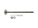 Chevrolet Corvette Axle Shaft
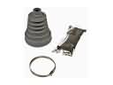 Chevrolet Corvette CV Boot
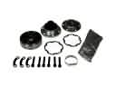 Chevrolet Corvette CV Joint
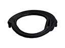 Chevrolet Corvette Coil Spring Insulator
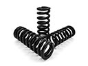 Chevrolet Corvette Coil Springs
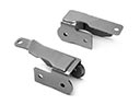 Chevrolet Corvette Control Arm Bracket
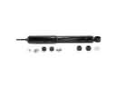 Chevrolet Corvette Shock Absorber
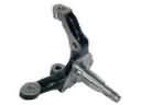 Chevrolet Corvette Spindle
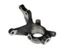 Chevrolet Corvette Steering Knuckle
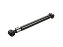 Chevrolet Corvette Suspension Strut Rod
 Chevrolet Corvette Sway Bar Bracket
 Chevrolet Corvette Sway Bar Bushing