ChevyParts
My Garage
My Account
Cart
OEM 2007 Cadillac DTS Upper Steering Column Bearing
Upper Tilt Steering Column Bearing- Select Vehicle by Model
- Select Vehicle by VIN
Select Vehicle by Model
orMake
Model
Year
Select Vehicle by VIN
For the most accurate results, select vehicle by your VIN (Vehicle Identification Number).
1 Upper Steering Column Bearing found


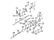
2007 Cadillac DTS Shaft Bearings Part Number: 26001827
$50.91 MSRP: $86.67You Save: $35.76 (42%)Ships in 1-3 Business DaysProduct Specifications- Other Name: Bearing Assembly, Steering Column; Bearing Assembly; Bearing Kit; Housing Bearing; Upper/Lower Bearings; Steering Column Bearings.
- Position: Upper
- Item Weight: 0.40 Pounds
- Item Dimensions: 1.4 x 1.5 x 0.4 inches
- Condition: New
- Fitment Type: Direct Replacement
- SKU: 26001827
- Warranty: This genuine part is guaranteed by GM's factory warranty.
2007 Cadillac DTS Upper Steering Column Bearing
With a comprehensive array of OEM 2007 Cadillac DTS Upper Steering Column Bearing, from fuel pumps to door handles, our website is a one-stop-shop for your needs. All our genuine 2007 Cadillac DTS Upper Steering Column Bearing are backed by the manufacturer's warranty and are offered at competitive prices in the market. Rest assured, you can shop with complete confidence.
2007 Cadillac DTS Upper Steering Column Bearing Parts and Q&A
- Q: How to replace the Upper Steering Column Bearing in a power tilt/telescope, column shift system on 2007 Cadillac DTS?A: System sir must be disabled before replacing the upper Steering Shaft bearing on power tilt/telescope, column shift vehicles. First detach the Steering Wheel from the Steering Column before removing the column from the car. Start by removing the Steering Wheel theft deterrent lock assembly and follow with the linear shift assembly before eliminating the shift lever and a/t shift lock control. Excise the turn signal assembly with multifunction switch and tilt spring and wire harness assembly and telescope drive motor assembly and cable and tilt drive motor assembly and cable from the system. A torx(R) head screw needs removal from the tilt and telescope module before users can pull the control module out from the Steering Column. Next remove these components from the column: boot seal, Steering Shaft seal, sensor retainer, sensor locator, and Steering Wheel position sensor. Dismantling a torx(R) head screw on the bracket's bottom section allows for the bracket's removal. Use the pivot pin remover (J 21854-01) to remove two pivot pins from the Steering Column support assembly after gently prying off the lower shield assembly from the column. Unscrew the lead screw to extract the tilt head assembly from the Steering Column support assembly maintaining the Steering Shaft attached. Detach the tilt head assembly from the Steering Shaft assembly followed by extracting the bearing assembly from the tilt head assembly. Before assembly start with the bearing assembly placed in the tilt head assembly followed by the integration of the Steering Shaft assembly into the tilt head assembly. Screw in the lead screw after you insert the Steering Column tilt head assembly and Steering Shaft assembly into the Steering Column jacket assembly. The Steering Column support assembly requires gm p/n 12345718 (Canadian P/N 10953516) for lubrication before installing the two pivot pins. Attach the lower shield assembly to its place on the Steering Column while snapping it into position. Put the bracket together with one torx(R) head screw at the bottom of the gearshift and tilt motor bracket before tightening the screw to 3 n.m (27 lb in). The installation order includes the Steering Wheel position sensor followed by sensor locator then sensor retainer followed by Steering Shaft seal and finishing with boot seal. The control module needs to be positioned correctly then secure with a single retaining screw at 5 n.m (44 lb in) torque setting. To complete the installation sequence, begin with the tilt drive motor assembly and cable along with the telescope drive motor assembly and cable and tilt spring. Next, install the turn signal and multifunction switch assembly and the linear shift assembly and shift lever. Then add the a/t shift lock control and wire harness assembly and Steering Wheel theft deterrent lock assembly. Once this is complete, reinstall the Steering Column into the vehicle before you can attach the Steering Wheel and activate the sir system.
Related 2007 Cadillac DTS Parts
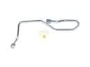 2007 Cadillac DTS Power Steering Hose
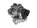 2007 Cadillac DTS Power Steering Pump
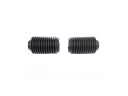 2007 Cadillac DTS Rack And Pinion
 2007 Cadillac DTS Steering Wheel
 2007 Cadillac DTS Power Steering Reservoir
 2007 Cadillac DTS Rack and Pinion Boot
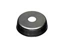 2007 Cadillac DTS Radius Heat Shield
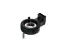 2007 Cadillac DTS Steering Angle Sensor
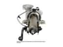 2007 Cadillac DTS Steering Column
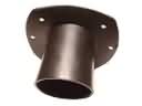 2007 Cadillac DTS Steering Column Seal
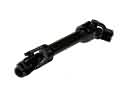 2007 Cadillac DTS Steering Shaft
 2007 Cadillac DTS Tie Rod End