ChevyParts
My Garage
My Account
Cart
OEM Cadillac Seville Control Arm
Suspension Arm- Select Vehicle by Model
- Select Vehicle by VIN
Select Vehicle by Model
orMake
Model
Year
Select Vehicle by VIN
For the most accurate results, select vehicle by your VIN (Vehicle Identification Number).
22 Control Arms found


Cadillac Seville Control Arm, Passenger Side Part Number: 25766510
$195.81 MSRP: $317.79You Save: $121.98 (39%)
Cadillac Seville Control Arm, Driver Side Part Number: 25766511
$195.81 MSRP: $317.79You Save: $121.98 (39%)


Cadillac Seville Control Arm, Rear Driver Side Part Number: 25820031

Cadillac Seville Lower Control Arm, Driver Side Part Number: 22156605

Cadillac Seville Control Arm, Rear Driver Side Part Number: 22156945

Cadillac Seville Control Arm, Driver Side Part Number: 1632883
Cadillac Seville Control Arm, Passenger Side Part Number: 1632884


Cadillac Seville Control Arm, Rear Driver Side Part Number: 22156335
Cadillac Seville Control Arm, Lower Part Number: 3544710
Cadillac Seville Control Arm, Driver Side Part Number: 25672983
Cadillac Seville Control Arm, Driver Side Part Number: 25672985
Cadillac Seville Control Arm, White, Lower Part Number: 3544705
Cadillac Seville Control Arm, White, Lower Part Number: 3544706
Cadillac Seville Control Arm, Lower Part Number: 3544709
Cadillac Seville Control Arm, Passenger Side Part Number: 25672986
Cadillac Seville Lower Control Arm, Driver Side Part Number: 22527859
| Page 1 of 2 |Next >
1-20 of 22 Results
Cadillac Seville Control Arm
Want to cut long-term maintenance and repair costs? Choose OEM Control Arm. Those parts deliver top durability you can trust. On our site, you'll find a huge catalog of genuine Cadillac Seville parts. Prices are unbeatable, so you can keep more in your pocket. Every OEM Cadillac Seville Control Arm includes a manufacturer's warranty. You can also get an easy return policy that keeps buying risk free. Fast delivery, get your car on the road quickly. It's simple to search, compare, and order. Stop guessing about quality or fit. Order today and save with parts that last.
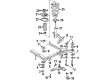
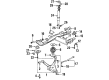
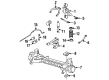
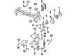
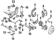
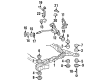
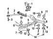
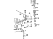
One of the currently used Cadillac Seville Control Arm is shown in the following image where it is found to be a key model that optimal represents the car's reliability and operational capacity. Being a main component, the Control Arm bridge the space between the frame of the car and its wheels in a way that assists the suspension system to function properly particularly in the aspect of wheel adjustment and control. This is highly relevant, especially for the Cadillac Seville, which marked its debut in 1975, though the birth of the first generation occurred in 1970, and stopped production in 2004. Such compatibility makes the customers of different Seville versions shift their driving efficiency and safety to the next level with the Control Arm. For the Seville Control arm Cadillac has used conventional stamped steel,Cast iron,Aluminum that adds more strenth and reduces the weight of the part. Performance-oriented Control Arms are also available that can be used in large engines and high-stress conditions and dimensional changes, which will make sure Cadillac Seville does not lose her character of superior road holding and stability. It also has bushings and ball joint of Control Arm and contributes to a comfortable ride for the driver. Hence, the Cadillac Seville Control Arm breaks the mold in the automotive market primarily because of the design and engineering that Cadillac places into each of their creations. Due to its sturdy build and its technologically enhanced attributes, the Control Arm facilitates the Cadillac Seville and thus forms a significant component of the automobile's success story.
Cadillac Seville Control Arm Parts and Q&A
- Q: How to replace the front lower control arm on Cadillac Seville?A:The front lower Control Arm replacement process begins with vehicle elevation for support followed by tire removal and wheel removal and subsequent removal of the stabilizer shaft link and road sensing suspension link from the lower Control Arm. To begin the installation start by removing both the lower ball joint cotter pin and retaining nut. Begin by using the ball joint separator (J43828) on the lower ball joint-Steering Knuckle assembly to free up both components. Finally remove the lower Control Arm mounting hardware to fully extract the arm. Begin installation by fitting the lower Control Arm to the frame but do not tighten the Control Arm nuts at first until reaching the design trim height while supporting the vehicle weight through the control arms. Place the lower ball joint stud into the Steering Knuckle before installing the lower ball joint retaining nut. Secure the lower Control Arm bolts and nuts at their proper positions. Tighten the lower ball joint stud nut to 10 nm (88 inch lbs.) before continuing to torque it an additional 150 degrees while keeping additional torque to less than 60 degrees for cotter pin installation. The installation process begins with the cotter pin followed by the road sensing suspension then the stabilizer shaft link and ends with tire and wheel installation. The vehicle needs to go down and then come up again to firm the lower Control Arm nuts to 157 nm (116 ft. Lbs.).
- Q: How to service and repair the control arm on Cadillac Seville?A:To service and repair the Control Arm, remove the rear support initially. Next, remove the stabilizer shaft link and the adjustment link retaining nut from the lower Control Arm. On one hand, separate the adjustment link from the lower Control Arm, using the universal steering linkage puller (J 24319-B), then take out the Wheel Bearing and hub from the lower Control Arm. On the other hand, manually pull the hub (usage of Universal Steering Linkage Puller (J 24319-B) is allowed) out of the lower Control Arm, allow the lower Control Arm to go back into the bushing, then replace the bolt and tighten it using 6" breaker bar. Getting down to the removal of the lower Control Arm mounting bolts and nuts and then the lower Control Arm. To install, bolt the lower Control Arm to the support while making sure that the Control Arm nuts are done without the help of a vehicle in an upright position and resting at the normal trim height. Install the lower Control Arm mounting bolts and nuts, the Wheel Bearing, as well as the hub. Mount the adjustment link onto the lower Control Arm while installing the adjustment link retaining nut tightening at 75 nm (55 ft.lbs). Then install the stabilizer shaft link, and rear support. Last, bring the vehicle down to the trim height, and secure the lower Control Arm mounting nuts to 106 nm (78 ft. Lbs.).


Related Cadillac Seville Parts
 Cadillac Seville Axle Pivot Bushing
 Cadillac Seville Ball Joint
 Cadillac Seville Coil Spring Insulator
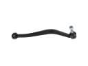 Cadillac Seville Lateral Arm
 Cadillac Seville Shock Absorber
 Cadillac Seville Steering Knuckle
 Cadillac Seville Sway Bar Bushing
 Cadillac Seville Sway Bar Link
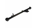 Cadillac Seville Trailing Arm
 Cadillac Seville Trailing Arm Bushing
 Cadillac Seville Wheel Hub
 Cadillac Seville Wheel Seal