ChevyParts
My Garage
My Account
Cart
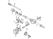
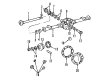
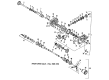
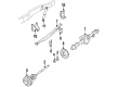
OEM Chevrolet Blazer Axle Shaft
Car Axle Shaft- Select Vehicle by Model
- Select Vehicle by VIN
Select Vehicle by Model
orMake
Model
Year
Select Vehicle by VIN
For the most accurate results, select vehicle by your VIN (Vehicle Identification Number).
72 Axle Shafts found


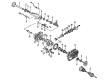
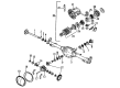
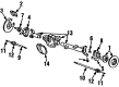
Chevrolet Blazer Pinion Shaft, Front Passenger Side Part Number: 19121909
$144.68 MSRP: $353.04You Save: $208.36 (60%)Ships in 1-2 Business Days
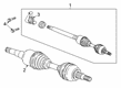
Chevrolet Blazer Axle Shaft, Front Part Number: 7849332
$49.28 MSRP: $88.00You Save: $38.72 (44%)Ships in 1-3 Business DaysChevrolet Blazer Axle Shaft, Front Part Number: 7849300
$51.92 MSRP: $92.72You Save: $40.80 (44%)Ships in 1-3 Business Days
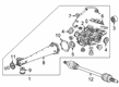
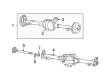
Chevrolet Blazer Axle Assembly, Front Passenger Side Part Number: 84878163
$275.61 MSRP: $473.37You Save: $197.76 (42%)Ships in 1-2 Business Days
Chevrolet Blazer Axle Shafts, Rear Part Number: 85150636
$103.97 MSRP: $253.67You Save: $149.70 (60%)Ships in 1-3 Business Days
Chevrolet Blazer Tube Part Number: 84703734
$298.76 MSRP: $470.09You Save: $171.33 (37%)Ships in 1-2 Business Days


Chevrolet Blazer Output Shaft, Front Driver Side Part Number: 26006824


Chevrolet Blazer Axle Shaft, Rear Part Number: 26050549

Chevrolet Blazer Axle Shafts, Rear Part Number: 12380993
Chevrolet Blazer Axle Shaft, Rear Part Number: 26027706
Chevrolet Blazer Axle Shaft, Rear Part Number: 26033365

Chevrolet Blazer Axle Shafts Part Number: 7844114

Chevrolet Blazer Axle Shaft Part Number: 14071750
Chevrolet Blazer Axle Shaft, Driver Side Part Number: 26015323

Chevrolet Blazer Axle Shaft, Front Part Number: 15521884

Chevrolet Blazer Stub Shaft, Front Part Number: 26034184
Chevrolet Blazer Axle Shaft, Inner Passenger Side Part Number: 458878
Chevrolet Blazer Axle Shaft, Rear Part Number: 26033364
Chevrolet Blazer Axle Shafts, Rear Part Number: 26058925
| Page 1 of 4 |Next >
1-20 of 72 Results
Chevrolet Blazer Axle Shaft
Our website offers an extensive catalog of genuine Chevrolet Blazer Axle Shaft at unbeatable prices. Every OEM Chevrolet Blazer Axle Shaft comes with a manufacturer's warranty, an easy return policy, and rapid delivery service. Don't miss out on this great opportunity!
Chevrolet Blazer Axle Shaft Parts Questions & Experts Answers
- Q: How to replace the wheel axle shaft on Chevrolet Blazer?A: The replacement process for an Axle Shaft begins by unlocking the Steering Column for steering linkage mobility followed by construction of the vehicle and applying suitable safety stands for stabilization. Insert a drift through the brake caliper into one of the rotor vanes before handling the two front tire and wheel assemblies and drive axle which needs to be prevented from turning. After taking out the drift from the brake rotor users should remove the axle nut along with its washer. The caliper should be suspended with wire while you remove its front rotors to prevent brake hose damage. The upper Control Arm needs its abs wire and brake hose brackets detached before removing the abs bracket from the Ball Joint of the upper Control Arm. Secure the frame to the hoist while preventing it from moving so the safety stand avoids damage to any system components. A safety stand should be positioned beneath the lower Control Arm for proper support of the Steering Knuckle assembly together with the lower Control Arm using another safety stand. Strike the axle outer end with a brass drift to detach the Axle Shaft through hammering. The Steering Knuckle assembly needs wire support to protect the outer tie rod and abs wire before workers can remove both the upper Ball Joint and lower shock absorber part. Push the differential carrier-end of the Axle Shaft toward the carrier to generate enough space for removing the knuckle assembly after you loosen the lower Ball Joint from the knuckle. Lower the safety stand from the lower Control Arm until Torsion Bar pressure decreases because clearance needs to expand without harming the axle seal. Proceed by removing the lower Ball Joint followed by the axle from the Steering Knuckle assembly. To disconnect the left and right side axle shafts from the differential carrier strike a piece of wooden or brass drift against the tripot housing until snap ring pressure is overcome. Then remove the front differential carrier shield. Begin the differential carrier axle removal by extracting it straight forward while your support keeps the boot from tearing. The operation of a vehicle becomes unsafe when the driver operates it without front axle nuts or shafts. Also the vehicle weight should never load the front wheels through its weight. Finally, remove the axle. A shop towel must cover all sharp edges on the shock mounting bracket and lower Control Arm ball stud to shield the boot from damage during installation. Install the Axle Shaft to the differential carrier through spline alignment while guiding the axle into the differential carrier seal and then drive the shaft straight until the snap ring seats. Enter the safety stand underneath the lower Control Arm weight before you begin slowly placing the knuckle onto the axle while putting the ball stud into the correct spot on the Steering Knuckle. The installation order includes lower Ball Joint and lower shock absorber section and the upper Ball Joint assembly. Begin by putting the axle washer and nut along with its proper torque of 140 nm (103 ft. Lbs.). Then install the abs bracket that sits on the upper Control Arm Ball Joint as well as components which hold the abs wire and brake hose will follow. First install the front brake rotors with the front differential carrier shield after removing the frame strap to install both front tire and wheel assemblies when the vehicle reaches the ground level.

Related Chevrolet Blazer Parts
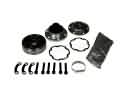 Chevrolet Blazer CV Joint
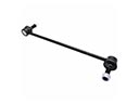 Chevrolet Blazer Sway Bar Link
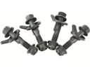 Chevrolet Blazer Alignment Bolt
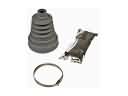 Chevrolet Blazer CV Boot
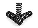 Chevrolet Blazer Coil Springs
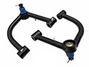 Chevrolet Blazer Control Arm
 Chevrolet Blazer Control Arm Bolt
 Chevrolet Blazer Leaf Spring
 Chevrolet Blazer Leaf Spring Bushing
 Chevrolet Blazer Sway Bar Bushing
 Chevrolet Blazer Torsion Bar
 Chevrolet Blazer Wheel Cover