ChevyParts
My Garage
My Account
Cart
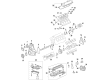
OEM Chevrolet Corvette Engine Mount
Engine Motor Mount- Select Vehicle by Model
- Select Vehicle by VIN
Select Vehicle by Model
orMake
Model
Year
Select Vehicle by VIN
For the most accurate results, select vehicle by your VIN (Vehicle Identification Number).
24 Engine Mounts found


Chevrolet Corvette Motor Mount, Driver Side Part Number: 23187451
$88.29 MSRP: $151.62You Save: $63.33 (42%)Ships in 1-2 Business Days

Chevrolet Corvette Motor Mount, Passenger Side Part Number: 23187454
$88.29 MSRP: $151.62You Save: $63.33 (42%)Ships in 1-2 Business Days

Chevrolet Corvette Mount Bracket, Driver Side Part Number: 23207231
$39.47 MSRP: $67.20You Save: $27.73 (42%)Ships in 1-2 Business Days


Chevrolet Corvette Motor Mount Part Number: 15254700
$80.15 MSRP: $136.45You Save: $56.30 (42%)Chevrolet Corvette Motor Mount, Passenger Side Part Number: 20980869
$88.29 MSRP: $151.62You Save: $63.33 (42%)Ships in 1-2 Business DaysChevrolet Corvette Motor Mount, Driver Side Part Number: 20980866
$88.29 MSRP: $151.62You Save: $63.33 (42%)Ships in 1-2 Business Days
Chevrolet Corvette Mount Bracket, Passenger Side Part Number: 25796382
$97.01 MSRP: $151.97You Save: $54.96 (37%)Ships in 1-3 Business DaysChevrolet Corvette Mount Bracket, Driver Side Part Number: 25796383
$95.85 MSRP: $150.15You Save: $54.30 (37%)Ships in 1-3 Business Days
Chevrolet Corvette Motor Mount, Passenger Side Part Number: 87819667
$97.88 MSRP: $153.28You Save: $55.40 (37%)Ships in 1-3 Business DaysChevrolet Corvette Mount Bracket, Passenger Side Part Number: 23207232
$39.59 MSRP: $67.97You Save: $28.38 (42%)Ships in 1-2 Business Days
Chevrolet Corvette Motor Mount, Passenger Side Part Number: 84675415
$88.58 MSRP: $138.72You Save: $50.14 (37%)Ships in 1-3 Business DaysChevrolet Corvette Motor Mount, Driver Side Part Number: 84675414
$95.30 MSRP: $149.26You Save: $53.96 (37%)Ships in 1-3 Business DaysChevrolet Corvette Motor Mount, Driver Side Part Number: 87819668
$102.41 MSRP: $160.39You Save: $57.98 (37%)Ships in 1-3 Business Days


Chevrolet Corvette Mount Bracket, Driver Side Part Number: 10260642

Chevrolet Corvette Mount Bracket, Driver Side Part Number: 10349964
Chevrolet Corvette Mount Bracket, Passenger Side Part Number: 10349965

Chevrolet Corvette Motor Mount Part Number: 10157980

Chevrolet Corvette Mount Bracket, Passenger Side Part Number: 14104624
Chevrolet Corvette Motor Mount Part Number: 25966517
$117.30 MSRP: $184.50You Save: $67.20 (37%)
Chevrolet Corvette Mount Brace Part Number: 14104626
| Page 1 of 2 |Next >
1-20 of 24 Results
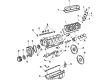
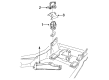
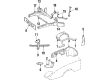
Chevrolet Corvette Engine Mount
Want to cut long-term maintenance and repair costs? Choose OEM Engine Mount. Those parts deliver top durability you can trust. On our site, you'll find a huge catalog of genuine Chevrolet Corvette parts. Prices are unbeatable, so you can keep more in your pocket. Every OEM Chevrolet Corvette Engine Mount includes a manufacturer's warranty. You can also get an easy return policy that keeps buying risk free. Fast delivery, get your car on the road quickly. It's simple to search, compare, and order. Stop guessing about quality or fit. Order today and save with parts that last.
Chevrolet Corvette Engine Mount Parts and Q&A
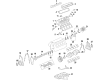
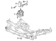
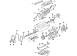
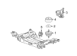
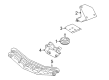
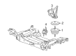
- Q: How to service and repair the engine mount on Chevrolet Corvette?A:Start the Engine Mount service and repair operation by taking out the generator from both accessory mounting bracket and washer solvent reservoir. Serially disconnect and safely place the engine coolant switch and front headlamp electrical connectors. The engine support fixture (J 41803) with universal engine support fixture (J 28467-B) should support the engine but ensure jacking occurs outside engine areas to prevent damage. First setup engine supports and then lift the vehicle to gain access to the wheels. Remove wheels and tires from the front side of the car. Use the ball joint separator (J 42188) to remove tie rod ends from the Steering Knuckles by unfastening their stud nuts. Worker should first remove the stabilizer shaft bolts while using tools to detach the links from lower Control Arms before taking out the stabilizer shaft. Move to the Power Steering Cooler which needs all bolts removed before disconnecting it from the crossmember. Then position the cooler upward. Install the transverse Leaf Spring compressor (J 33432-A) between the spring by attaching it to the spring then start compression. Start removing shock absorber lower mounting bolts before loosening the lower ball joint nuts to separate lower ball joints with ball joint separator (J 42188). Detach all electrical wires from the crossmember followed by removing brake pressure modulator valve bracket bolts then move both the ebtcm/bpmv and its bracket out of the crossmember area. Place a transmission jack under the crossmember while removing its mounting nuts extensively before discarding the nuts. The procedure starts with removing both the transmission jack and the crossmember followed by removal of the upper Engine Mount nut and subsequent removal of the Engine Mount itself. The installation procedure calls for scrapping bracket bolts from both the engine block and the bracket if necessitated. The first step for installation begins with mounting the engine bracket followed by tightening its bolts to 50 nm (37 ft. Lbs.). Install the upper mount stud first then the nut while facing up the metal end of the mount and properly positioning the locating dowels before tightening the nut to 65 nm (48 ft. Lbs.). Begin by installing the crossmember followed by new nuts which require tightening force of 110 nm (81 ft. Lbs.). Then repeat this step by installing the Engine Mount lower stud-to-crossmember nuts while tightening them to 65 nm (48 ft. Lbs.). Rewire all electrical wires to the crossmember clips while you also mount the brake pressure modulator valve bracket using 27 nm (20 ft. Lbs.) torque specification. After placing the transverse Leaf Spring onto the crossmember you should install the shock absorber lower mounting bolts while torquing them to 28 nm (20 ft. Lbs.). Reinstall the lower Control Arm ball joint studs to the steering knuckles before securing the corresponding nuts by tightening them to 70 nm (52 ft. Lbs.). After removing the transverse Leaf Spring compressor (J 33432-A) from the spring position install the power steering gear while secure its bolts at 100 nm (74 ft. Lbs.). After reinstallation of the Power Steering Cooler you should tighten its bolts up to a torque of 11 nm (97 inch lbs.). Fit the front stabilizer shaft to the crossmember then install Tie Rod End studs to steering knuckles along with their nuts and tighten to 45 nm (33 ft. Lbs.). Put front tire and wheel assemblies back then torque wheel nuts to 140 nm (100 ft. Lbs.) before returning the vehicle to its previous height and taking off the engine support fixture (J 41803), universal engine support fixture (J 28467-B) from the engine. Put back the washer solvent reservoir followed by engine coolant switch and front headlamp electrical connector installation then mount the generator to the accessory bracket.
- Q: How to replace the left engine mount on Chevrolet Corvette?A:The first step to replace the left Engine Mount requires removal of the front suspension crossmember. After removing the Engine Mount-to-Engine Mount bracket nut you should take out the Engine Mount itself. The Engine Mount heat shield must be disconnected from the Engine Mount if required. Start by attaching the Engine Mount heat shield to the mount before installing the mount in its correct position. The installation of the Engine Mount-to-Engine Mount bracket nut needs strict compliance to the fastener notice in service precautions while performing the torque to 65 nm (48 ft. Lbs.). Reinstall the front suspension crossmember as the last step.


Related Chevrolet Corvette Parts
 Chevrolet Corvette Camshaft Bearing
 Chevrolet Corvette Dipstick
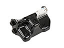 Chevrolet Corvette Engine Mount Bracket
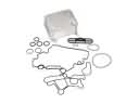 Chevrolet Corvette Engine Oil Cooler
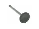 Chevrolet Corvette Intake Valve
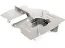 Chevrolet Corvette Oil Pan Baffle
 Chevrolet Corvette Oil Pump
 Chevrolet Corvette Oil Pump Gasket
 Chevrolet Corvette Piston Ring
 Chevrolet Corvette Rocker Shaft Spring Kit
 Chevrolet Corvette Timing Chain Guide
 Chevrolet Corvette Variable Timing Sprocket