ChevyParts
My Garage
My Account
Cart
OEM Chevrolet Silverado 1500 Fuel Rail
Engine Fuel Rail- Select Vehicle by Model
- Select Vehicle by VIN
Select Vehicle by Model
orMake
Model
Year
Select Vehicle by VIN
For the most accurate results, select vehicle by your VIN (Vehicle Identification Number).
28 Fuel Rails found


Chevrolet Silverado 1500 Fuel Rail Part Number: 97361353
$336.68 MSRP: $683.83You Save: $347.15 (51%)


Chevrolet Silverado 1500 Fuel Rail Part Number: 12602113
$114.68 MSRP: $232.93You Save: $118.25 (51%)Ships in 1-2 Business Days


Chevrolet Silverado 1500 Fuel Rail Part Number: 17113695
$104.95 MSRP: $327.45You Save: $222.50 (68%)Ships in 1-2 Business Days


Chevrolet Silverado 1500 Fuel Rail Part Number: 12621662
$188.56 MSRP: $341.28You Save: $152.72 (45%)Ships in 1-2 Business Days


Chevrolet Silverado 1500 Fuel Rail Part Number: 97361352
$351.85 MSRP: $714.61You Save: $362.76 (51%)
Chevrolet Silverado 1500 Fuel Rail Part Number: 12621665
$184.53 MSRP: $374.78You Save: $190.25 (51%)Ships in 1-2 Business DaysChevrolet Silverado 1500 Fuel Rail Part Number: 12688001
$98.97 MSRP: $176.74You Save: $77.77 (44%)Ships in 1-3 Business DaysChevrolet Silverado 1500 Fuel Rail Part Number: 55505909
$198.35 MSRP: $355.78You Save: $157.43 (45%)Ships in 1-3 Business DaysChevrolet Silverado 1500 Fuel Rail Part Number: 12707885
$107.92 MSRP: $192.72You Save: $84.80 (44%)Ships in 1-2 Business DaysChevrolet Silverado 1500 Fuel Rail Part Number: 12707886
$107.92 MSRP: $192.72You Save: $84.80 (44%)Ships in 1-2 Business DaysChevrolet Silverado 1500 Fuel Rail Part Number: 12733958
$105.75 MSRP: $188.84You Save: $83.09 (44%)Ships in 1-2 Business Days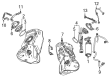
Chevrolet Silverado 1500 Fuel Rail Part Number: 12729464
$117.50 MSRP: $238.66You Save: $121.16 (51%)Ships in 1-2 Business Days
Chevrolet Silverado 1500 Fuel Rail Part Number: 12729466
$117.50 MSRP: $238.66You Save: $121.16 (51%)Chevrolet Silverado 1500 Fuel Rail Part Number: 12621668
$198.77 MSRP: $359.76You Save: $160.99 (45%)Ships in 1-2 Business DaysChevrolet Silverado 1500 Fuel Rail Part Number: 40009114
$134.63 MSRP: $273.44You Save: $138.81 (51%)Chevrolet Silverado 1500 Fuel Rail Part Number: 12719353
$128.28 MSRP: $229.32You Save: $101.04 (45%)Ships in 1-3 Business Days


Chevrolet Silverado 1500 Fuel Rail Part Number: 17113696


Chevrolet Silverado 1500 Fuel Rail Part Number: 97303659


Chevrolet Silverado 1500 Fuel Rail Part Number: 97208075
Chevrolet Silverado 1500 Fuel Rail Part Number: 17113547
| Page 1 of 2 |Next >
1-20 of 28 Results
Chevrolet Silverado 1500 Fuel Rail
Want to cut long-term maintenance and repair costs? Choose OEM Fuel Rail. Those parts deliver top durability you can trust. On our site, you'll find a huge catalog of genuine Chevrolet Silverado 1500 parts. Prices are unbeatable, so you can keep more in your pocket. Every OEM Chevrolet Silverado 1500 Fuel Rail includes a manufacturer's warranty. You can also get an easy return policy that keeps buying risk free. Fast delivery, get your car on the road quickly. It's simple to search, compare, and order. Stop guessing about quality or fit. Order today and save with parts that last.
Chevrolet Silverado 1500 Fuel Rail Parts and Q&A
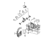
- Q: How to install the fuel injector and fuel rail on Chevrolet Silverado 1500?A:Align the installation process with new Fuel Injector O-Ring seals (532, 534) which should receive engine oil lubrication before mounting onto fuel injectors (533). The sequence starts with fuel injectors and retainers (521) installation before attaching the fuel rail assembly (510) to the manifold through forceful side-to-side presses until each injector fits its bore. The threads of fuel rail bolts (511) need threadlock gm p/n 12345382 (Canadian P/N 10953489) applied as a 5 mm (0.2 in) band followed by tightening these bolts to 10 n.m (89 lb in). The next installation step involves adding the evap canister purge solenoid valve (730) together with tubes (729, 735) while finishing by tightening the bracket bolt to 50 n.m (37 lb ft).
- Q: How to replace the Fuel Injection Fuel Rail Assembly on Chevrolet Silverado 1500?A:You should start by taking off the air cleaner outlet duct before lowering fuel system pressure with ch 48027 or without it to perform fuel injection Fuel Rail assembly replacement. First remove the engine wiring harness bracket nut while disconnecting all electrical connectors from the evap purge solenoid generator MAP Sensor and ignition coil main electrical connector and electronic throttle control. Proceed by disconnecting and noting the fuel injector electrical connectors before removing any necessary cpa retainers from the unit. All necessary steps include detaching engine wiring harness clips (4 and 6) and the negative Battery Cable stud along with terminals (2 and 3) from the Cylinder Head. You should disconnect the chassis fuel feed pipe as well as the evap tube quick connect fittings while disengaging the evap canister purge solenoid retainer and removing the Fuel Rail bolts. Raise the Fuel Rail assembly with caution while maintaining safety of injector electrical connectors and spray tips before sealing plugged pipe fittings to avoid system contamination. Apply a spray type engine cleaner to the Fuel Rail before you take out the fuel injector retainers and injectors while discarding both the top and bottom o-ring seals (2 and 4). You should first detach the crossover pipe retainer screws and retainers then remove the crossover pipe along with its o-ring seals from the system. Apply clean engine oil to the new o-ring seals before placing them onto the crossover pipe and inserting this pipe between the fuel rails where retainers and screws should be tightened to 3.8 n.m (34 lb in). After applying lubrication to new o-ring seals numbers 2 and 4 the technician installs the rubber seals on the fuel injectors before inserting them into the fuel rails to retain them with proper hardware. Use firm pressure to insert the Fuel Rail onto the intake manifold until all injectors are properly positioned. Install Fuel Rail bolts along with their matching torque to 10 n.m (89 lb in). The evap tube should be connected first followed by the purge solenoid and then the evap canister purge solenoid to the Fuel Rail bracket before installing the chassis fuel feed pipe and evap tube fittings. Reinstall the pcv hose and gather all engine wiring harness branches before using the clip bolt to secure them tightly to 9 n.m (80 lb in). Complete battery connection starts with attaching the negative Battery Cable terminal while installing the ground terminal followed by tightening the negative Battery Cable stud to 25 n.m (18 lb ft). The ignition coil main electrical connector needs to reconnect before installing the cpa retainer while also uniting electronic throttle control and fuel injector connectors properly with full security in place. The installation process ends by joining the MAP Sensor with the generator and evap purge solenoid followed by installing the engine wiring harness bracket nut with 5 n.m (44 lb in) torque and negative Battery Cable reconnection. Leak inspection should occur by turning the ignition on and off. The installation ends with ducting the airflow to the air cleaner after completion.

Related Chevrolet Silverado 1500 Parts
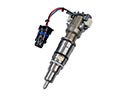 Chevrolet Silverado 1500 Fuel Injector
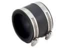 Chevrolet Silverado 1500 Air Intake Coupling
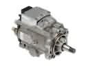 Chevrolet Silverado 1500 Fuel Injection Pump
 Chevrolet Silverado 1500 Fuel Injector O-Ring
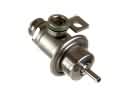 Chevrolet Silverado 1500 Fuel Pressure Regulator
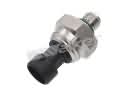 Chevrolet Silverado 1500 Fuel Pressure Sensor
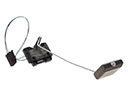 Chevrolet Silverado 1500 Fuel Tank Sending Unit
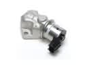 Chevrolet Silverado 1500 Idle Control Valve
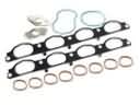 Chevrolet Silverado 1500 Intake Manifold Gasket
 Chevrolet Silverado 1500 Mass Air Flow Sensor
 Chevrolet Silverado 1500 Throttle Body
 Chevrolet Silverado 1500 Turbocharger