ChevyParts
My Garage
My Account
Cart
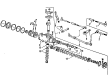
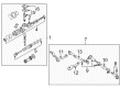
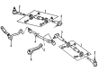
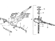
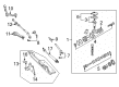
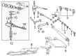
OEM GMC Sonoma Tie Rod
Steering Tie Rod- Select Vehicle by Model
- Select Vehicle by VIN
Select Vehicle by Model
orMake
Model
Year
Select Vehicle by VIN
For the most accurate results, select vehicle by your VIN (Vehicle Identification Number).
15 Tie Rods found

GMC Sonoma Tie Rod End, Inner Part Number: 7837183
$38.01 MSRP: $51.67You Save: $13.66 (27%)Ships in 1-2 Business Days
GMC Sonoma Outer Tie Rod Part Number: 26041018
$24.65 MSRP: $49.51You Save: $24.86 (51%)GMC Sonoma Inner Tie Rod Part Number: 26041016
$44.91 MSRP: $90.18You Save: $45.27 (51%)
GMC Sonoma Outer Tie Rod Part Number: 26029999
$21.13 MSRP: $42.44You Save: $21.31 (51%)
GMC Sonoma Tie Rod End, Inner Part Number: 7833122

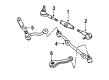
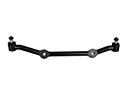
GMC Sonoma Center Link Part Number: 26055302
GMC Sonoma Outer Tie Rod Part Number: 26054936
GMC Sonoma Inner Tie Rod Part Number: 26054934
GMC Sonoma Center Link Part Number: 26038989
GMC Sonoma Center Link Part Number: 26038980

GMC Sonoma Center Link Part Number: 26031952
GMC Sonoma Inner Tie Rod Part Number: 26029995
GMC Sonoma Outer Tie Rod Part Number: 14050634

GMC Sonoma Inner Tie Rod Part Number: 12471301

GMC Sonoma Outer Tie Rod Part Number: 12471300
GMC Sonoma Tie Rod
Want to cut long-term maintenance and repair costs? Choose OEM Tie Rod. Those parts deliver top durability you can trust. On our site, you'll find a huge catalog of genuine GMC Sonoma parts. Prices are unbeatable, so you can keep more in your pocket. Every OEM GMC Sonoma Tie Rod includes a manufacturer's warranty. You can also get an easy return policy that keeps buying risk free. Fast delivery, get your car on the road quickly. It's simple to search, compare, and order. Stop guessing about quality or fit. Order today and save with parts that last.
GMC Sonoma Tie Rod Parts Questions & Experts Answers
- Q: How to replace a tie rod on GMC Sonoma?A:The replacement of the Tie Rod begins by raising and supporting the vehicle with safety stands installed. The procedure starts with removing the cotter pin along with the outer Tie Rod ball stud nut then moving to take off the inner Tie Rod ball stud nut. The joints in the steering linkage should remain undamaged when using any techniques for disassembly instead of a wedge. The j 24319-b steering linkage and Tie Rod puller should be used for removing the outer Tie Rod ball stud from the steering knuckle and the j 6627-a Tie Rod puller for extracting the inner Tie Rod ball stud from the relay rod. First disconnect the adjuster tube Tie Rod ends by loosening bolt clamps while rotating the assemblies out. Check the Tie Rod ends together with their seals as well as threads and adjuster tube for any evidence of damage. Thoroughly clean both ball stud threads and ball stud nut in addition to the tapered surfaces. The Tie Rod ends require chassis lubrication after removal but the threads of both main elements must be identical within three threads. To assemble the Tie Rod ends properly install them to the adjuster tube and join the inner rod ball stud to the relay rod with the seal facing the stud before using the j 29193 steering linkage installer (12 mm) or j 29194 steering linkage installer (14 mm) to torque the taper to 54 nm (40 ft. Lbs.). Secure the outer Tie Rod ball stud nut to 53 nm (39 ft. Lbs.) force while avoiding moving the nut to reach the cotter pin hole. The new cotter pin should be installed and then its ends must be opened to their fullest extent. Deenergize the steering wheel and place the vehicle onto the ground while you perform front toe adjustment. Set the two clamps between locating dimples located at the ends of the adjuster tube but avoid lining up the clamp slot with the adjuster tube slot. Each Tie Rod End must stay in position during clamp tightening according to specified requirements while the ends can be allowed to touch if needed. The last step involves tightening the adjuster tube clamp bolts until they reach 21 nm (16 ft. Lbs.).

Related GMC Sonoma Parts
 GMC Sonoma Center Link
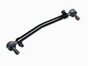 GMC Sonoma Drag Link
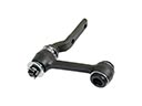 GMC Sonoma Idler Arm
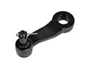 GMC Sonoma Pitman Arm
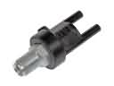 GMC Sonoma Power Steering Control Valve
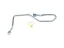 GMC Sonoma Power Steering Hose
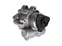 GMC Sonoma Power Steering Pump
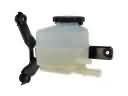 GMC Sonoma Power Steering Reservoir
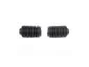 GMC Sonoma Rack And Pinion
 GMC Sonoma Steering Gearbox
 GMC Sonoma Tie Rod Adjusting Sleeve
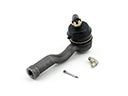 GMC Sonoma Tie Rod End