ChevyParts
My Garage
My Account
Cart
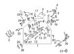
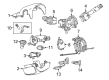
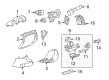
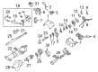
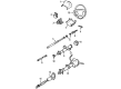
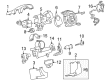
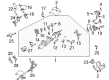
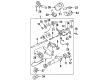
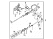
OEM GMC Steering Angle Sensor
Steering Column Angle Position Sensor- Select Vehicle by Model
- Select Vehicle by VIN
Select Vehicle by Model
orMake
Model
Year
Select Vehicle by VIN
For the most accurate results, select vehicle by your VIN (Vehicle Identification Number).
15 Steering Angle Sensors found


GMC Position Sensor Part Number: 19418403
$59.50 MSRP: $102.20You Save: $42.70 (42%)Product Specifications- Other Name: Sensor Assembly, Steering Wheel Position; Steering Wheel Speed Sensor; Steering Angle Sensor; Sensor, Steering Column
- Replaces: 20910871


GMC Angle Sensor Part Number: 25849366
$49.84 MSRP: $96.72You Save: $46.88 (49%)Ships in 1-2 Business DaysProduct Specifications- Other Name: Sensor, Steering Gear Hydraulic Valve; Steering Wheel Speed Sensor; Steering Angle Sensor; Steering Sensor Assembly


GMC Position Sensor Part Number: 84107026
$54.17 MSRP: $106.07You Save: $51.90 (49%)Product Specifications- Other Name: Sensor, Steering Gear Hydraulic Valve; Steering Wheel Speed Sensor; Steering Angle Sensor; Angle Sensor
- Replaces: 20795490


GMC Angle Sensor Part Number: 26109034
$130.37 MSRP: $255.23You Save: $124.86 (49%)Ships in 1-2 Business DaysProduct Specifications- Other Name: Sensor, Steering Column; Steering Wheel Speed Sensor; Steering Angle Sensor


GMC Position Sensor Part Number: 26104070
$129.89 MSRP: $254.28You Save: $124.39 (49%)Ships in 1-2 Business DaysProduct Specifications- Other Name: Sensor, Steering Column; Steering Wheel Speed Sensor; Steering Angle Sensor
- Replaces: 26100011


GMC Position Sensor Part Number: 13590209
$73.36 MSRP: $142.38You Save: $69.02 (49%)Ships in 1-2 Business DaysProduct Specifications- Other Name: Sensor, Steering Gear Hydraulic Valve; Steering Wheel Speed Sensor; Steering Angle Sensor; Angle Sensor; Sensor


GMC Position Sensor Part Number: 13589991
$41.83 MSRP: $116.38You Save: $74.55 (65%)Ships in 1-2 Business DaysProduct Specifications- Other Name: Sensor, Steering Gear Hydraulic Valve; Steering Wheel Speed Sensor; Steering Angle Sensor; Angle Sensor; Steering Sensor Assembly
- Replaces: 13579709, 13589257, 13584209, 13513905

GMC Angle Sensor Part Number: 13550726
$60.18 MSRP: $94.27You Save: $34.09 (37%)Ships in 1-2 Business DaysProduct Specifications- Other Name: Sensor, Steering Gear Hydraulic Valve
- Replaced by: 13558179

GMC Pressure Sensor Part Number: 84868124
$104.87 MSRP: $178.54You Save: $73.67 (42%)Ships in 1-3 Business DaysProduct Specifications- Other Name: Sensor Kit, Steering
- Replaces: 23372526


GMC Position Sensor Part Number: 26084178
Product Specifications- Other Name: Sensor, Steering Column; Steering Wheel Speed Sensor; Steering Angle Sensor


GMC Position Sensor Part Number: 25853012
Product Specifications- Other Name: Sensor, Steering Gear Hydraulic Valve; Steering Wheel Speed Sensor; Steering Angle Sensor; Angle Sensor


GMC Position Sensor Part Number: 15886733
Product Specifications- Other Name: Sensor, Steering Column; Steering Wheel Speed Sensor; Steering Angle Sensor
- Replaces: 15112675, 25833069


GMC Angle Sensor Part Number: 15115918
Product Specifications- Other Name: Sensor, Steering Gear Hydraulic Valve; Steering Wheel Speed Sensor; Steering Angle Sensor


GMC Speed Sensor Part Number: 26064468
$72.07 MSRP: $128.70You Save: $56.63 (44%)Product Specifications- Other Name: Sensor, Steering Column; Steering Wheel Speed Sensor; Steering Angle Sensor; Position Sensor; Sensor

GMC Position Sensor Part Number: 26091590
Product Specifications- Other Name: Sensor Kit, Steering; Steering Wheel Speed Sensor; Sensor
- Position: Rear
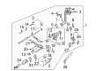
GMC Steering Angle Sensor
Want to cut long-term maintenance and repair costs? Choose OEM Steering Angle Sensor. Those parts deliver top durability you can trust. On our site, you'll find a huge catalog of genuine GMC parts. Prices are unbeatable, so you can keep more in your pocket. Every OEM GMC Steering Angle Sensor includes a manufacturer's warranty. You can also get an easy return policy that keeps buying risk free. Fast delivery, get your car on the road quickly. It's simple to search, compare, and order. Stop guessing about quality or fit. Order today and save with parts that last.
GMC Steering Angle Sensor Parts Questions & Experts Answers
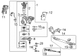
- Q: How to replace the rear Steering Angle Sensor on GMC Sierra 1500?A:Introduction starts with sensor replacement for the rear position sensor by elevating the vehicle in position. The electrical connector needs disconnection when removing the steering gear protection shield retaining bolts . The rear wheel position sensor cover needs to be removed from around the steering gear while protecting the rear position sensor from damage. Then loosen the bolts which retain the position sensor while inspecting the inner tie rod boot for signs of damage. Steering gear actuators need replacing if they become damaged. First maintain the sensor position without rotating it before taking the rear wheel position sensor out of the steering gear. Installation requires O-ring installation followed by rear wheel position sensor attachment to the steering gear with exact placement of the new sensor. Right away install the pin that retains the standard sensor position after removing it. Put rear wheel position sensor retaining bolts in position while using LOCTITE 242 blue fluid and torque them to 4 Nm (35 inch lbs.). Install the rear wheel position sensor cover and secure the electrical connector before installing the steering gear protection shield . Tighten all retaining bolts to 180 Nm (132 ft. lbs.). After setting the vehicle height use the four-wheel alignment equipment to calibrate all wheels.
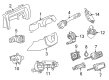
- Q: What tools are required to service and repair the Steering Angle Sensor on GMC Sierra 3500?A:The repair of the steering wheel position sensor requires these essential tools: Steering Column anti-rotation pin (J 42640). Steering Column anti-rotation pin (J 42640). The first step involves both the sir system disablement and locking the Steering Column from the access hole with a Steering Column anti-rotation pin (J 42640). Disconnecting the Steering Column or intermediate shaft without first locking the column in position and achieving straight-front wheel alignment will result in sir coil assembly damage and improper alignment. When installing a new sensor always check it includes the pin. Extract the vehicle's Steering Column after making sure the new sensor contains this pin. If not, reorder the sensor. The sensor connector requires a suitable tool to lower it down so the connection can be accessed while removing the sensor retainer from the Steering Shaft. Before reusing a sensor install a pin into it to keep it properly centered; otherwise discard it. Otherwise, discard the sensor. Leaving the bearing adapter in position remains crucial. To replace sensors maintain a direct pull which extracts them from the bearing adapter toward the Steering Shaft. Keep the sensor straight when fitting it onto the Steering Shaft before inserting it inside the bearing adapter. Never apply torque to the sensor during installation. The sensor needs to be adjusted to create a 3 mm distance between itself and the bearing adapter. Place the sensor connector onto the rotational sensor before pulling its pin off while mounting the two-part sensor retainer on the Steering Shaft. Reinstall the Steering Column to the vehicle after you remove the Steering Column anti-rotation pin (J 42640) then activate the sir system.
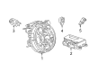
- Q: How to center the Steering Angle Sensor on GMC Yukon?A:Before centering the Steering Angle Sensor always double-check that the vehicle has straight wheels and implement a steering anti-rotation pin or column lock or strap to keep the wheel static to shield the sir system from breakdown. Steering column removal must occur together with intermediate shafts and steering gear disconnection but the wheel movement or tire position adjustment must remain static otherwise the sir coil centering will be lost. To fix an un-centered sir coil operate with the correct procedure for sir coil centering. Check the sensor type before removing it to establish proper connector positioning according to viewing it from the sensor's front. The centering process becomes unnecessary whenever you choose to reuse your existing sensor. Extract the adapter with both its connector and sensor from the bearing assembly. During installation position the sensor along the Steering Shaft while making sure the connector remains correctly connected. When working with a new sensor maintain control of the pin until the sensor reaches its final position. Flushing rotor flange cuffs should obtain alignment marks before sensor reuse to maintain proper orientation during sensor reinstallation. Specific features of the sensor should include pin holes for centering and alignment marks and foam rings which need to be documented when removing and installing the sensor to maintain proper functioning.


Related GMC Parts
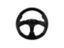 GMC Steering Wheel
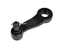 GMC Pitman Arm
 GMC Rack And Pinion
 GMC Steering Column Cover
 GMC Steering Shaft
 GMC Fuel Line Clamps
 GMC Ignition Lock Assembly
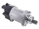 GMC Power Steering Assist Motor
 GMC Power Steering Pressure Switch
 GMC Radius Heat Shield
 GMC Steering Gearbox
 GMC Tie Rod End
Browse GMC Steering Angle Sensor by Models
Acadia Sierra 1500 Yukon Sierra 2500 HD Terrain C1500 K1500 Safari Savana 2500 Savana 3500 Sierra 2500 Sierra 3500 Yukon XL Acadia Limited C2500 C3500 K2500 K3500 Savana 1500 Yukon XL 1500 C1500 Suburban C2500 Suburban K1500 Suburban K2500 Suburban Sierra 1500 Classic Sierra 1500 HD Sierra 1500 HD Classic Sierra 1500 Limited Sierra 2500 HD Classic Sierra 3500 Classic Sierra 3500 HD Yukon XL 2500