
Popular OEM Cadillac Escalade EXT Parts
- Body & Hardware Parts View More >
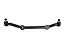
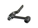
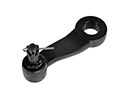
- Steering Parts View More >
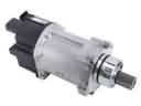
- Electrical Parts View More >
- Air & Fuel Delivery Parts View More >
- Charging & Starting Parts View More >
- Engine Parts View More >
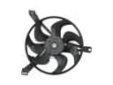
- Belts & Cooling Parts View More >
- Suspension Parts View More >
- Driveline & Axles Parts View More >
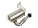
- Emission Control & Exhaust Parts View More >
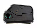
- Transmission Parts View More >
- Brakes Parts View More >

Why Buy Genuine Cadillac Escalade EXT Parts From ChevyPartsGiant.com
Looking for real Cadillac Escalade EXT parts? ChevyPartsGiant.com may be a better choice to find genuine parts at wallet-friendly prices. We sell only OEM Cadillac Escalade EXT parts, ensuring perfect fit, reliability, and long-term performance. With our website, you can easily get access to the same parts found at local Cadillac stores. All components are produced by Cadillac and are exclusively fitted on Cadillac Escalade EXT automobiles. By shopping at our store, you can enjoy the quality of the Cadillac factory without the high prices of brick-and-mortar facilities. We achieve this because we are an online store operating at lower costs, which we pass on to you. We also have a user-friendly platform where you can find and order genuine Cadillac Escalade EXT parts swiftly. We are here to make your process of restoring a Cadillac Escalade EXT or dealing with simple repairs quick and inexpensive. We also make it easy to obtain Cadillac Escalade EXT parts at competitive shipping prices and a team of knowledgeable staff ready to take your order. Choose ChevyPartsGiant.com to save time and money, as well as keep your Cadillac Escalade EXT in the good condition.
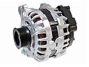
In 2002 Cadillac introduced the EXT version of the Escalade SUT which brought together the high-end features of the Escalade SUV and a pickup bed for more versatile functionality. A 6.0-liter V8 engine generating 345 horsepower powered the Cadillac Escalade EXT while it featured a standard all-wheel-drive system with a four-speed automatic transmission. The 2003 Escalade EXT received HID headlamps and a better StabiliTrak system then in 2005 it introduced a redesigned alternator along with touch-screen navigation. In 2007 the Cadillac Escalade EXT received a new 6.2-liter V8 engine that produced 403 horsepower along with a six-speed automatic transmission to boost driving performance and dynamics. The pushrod engine design excludes an overhead camshaft to optimize variable camshaft timing for the operation of both intake and exhaust valves. The active fuel management technology launched in 2010 came with additional enhancements that improved vehicle efficiency. The innovative Midgate system in the Cadillac Escalade EXT enables the rear cabin wall to fold down which increases the cargo bed length to 8 feet 2 inches from 5 feet 3 inches. The use of genuine parts in manufactured components stands as Cadillac Escalade EXT's primary objective because they create dependable and sturdy parts essential for maintaining both performance standards and luxury features of the Cadillac Escalade EXT.
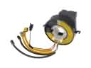
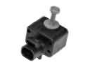
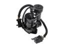
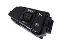
Cluster into chassis control electronics, fuel delivery, and intake air management are the issues that concern the Cadillac Escalade EXT to be diagnosed. A malfunctioning steering wheel position sensor is also typical of a Cadillac Escalade EXT with a chassis system that has a service stability message. Scan codes, check power and ground, replace the sensor, and lastly, perform the calibration. An Escalade EXT with long stalling or cranking time, in fuel delivery, normally has low rail pressure with a weak fuel pump. Check pressure, check relay command, check connectors, and change the fuel pump when the output is low. Together with intake air, it is typical to detect carbon inside the throttle body of an Escalade EXT that idles low or stalls at the stoplight. Clean throttle body, retune idle trims and complete closed throttle relearn. During a repair, Escalade EXT should be in a steady idle condition, must have a correct pressure, and it must regain stability control. Measure Cadillac service data of torque, wiring, and calibrations. Road test, check for no new codes, and record results. Preventive maintenance protects Cadillac drivability and reliability. The use of authorized procedures and quality elements must help the Escalade EXT to be predictable in its daily applications.
Cadillac Escalade EXT Parts Questions & Answers
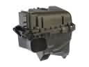
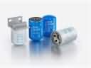
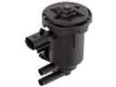
- Q: How to replace the underhood fuse box on Cadillac Escalade EXT?A:The replacement of the underhood electrical center or junction block requires disconnecting the negative Battery Cable first. A user should begin by lowering the electrical center brace cover while pushing its outboard tabs. Next, they should remove the left fender upper brace. Depress the tab after removing all fuses to move the electrical center through the studs positioned at . Separate all electrical connectors by unscrewing the bolt on each one then disconnect the wire ends from the electrical center block. The tabs should be pressed simultaneously to remove the electrical center from its housing. The replacement of engine electrical center bracket requires bolt removal from four retaining positions followed by bracket extraction from the fender. You can integrate the engine electrical center bracket assembly to the front fender through the installation sequence which requires 4 retaining bolts tightened at 9 n.m (80 lb in). Carefully fit the electrical center block stubs into position so that the tabs maintain its place inside the slots before tightening the wire connector bolts at 9 n.m (80 lb in) to the lower electrical center block portion. Connect all wire connectors securely after which set the electrical center block to its resting position to allow tabs to lock in position. After installation of the lower cover part begins the Fuse and relay installation while the cover remains open according to the Fuse location labels. The fender upper brace requires reinstallation while you secure it with the 4 bolts which must be tightened to 25 n.m (18 lb ft). After connecting the negative Battery Cable users must start the vehicle while checking that each component operates correctly.
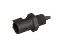
- Q: How to replace the Heated Oxygen Sensor (HO2S) for Bank 2 Sensor 1 in the 1500 Series on Cadillac Escalade EXT?A:Begin Heated Oxygen Sensor (HO2S) for Bank 2 Sensor 1 replacement in 1500 Series vehicles by raising the vehicle and supporting it for work. Detach the HO2S electrical connector from its position with the engine wiring harness electrical connector . Also remove the connector position assurance (CPA) retainer. The procedure continues with removal of the HO2S clip from the engine wiring harness followed by sensor extraction. Protect sensor connectors by avoiding any harm to the pigtail since damage may result in performance issues. The threads of new or service-replaced sensors should receive application of anti-seize compound GM P/N 12377953 or equivalent material to assist future uninstalls. Use anti-seize compound GM P/N 12377953 or equivalent on the HO2S threads before installation and torque it to 42 N.m (31 lb ft). Return the HO2S electrical connector to connect with the engine wiring harness electrical connector before fastening the CPA retainer and attaching the HO2S clip to the harnesses before lowering the vehicle.
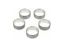
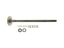
- Q: How to replace the Front Drive Axle Inner Wheel Seal and Inner Shaft Bearing on Cadillac Escalade EXT?A:The replacement process of front drive axle inner shaft seal and inner shaft bearing requires these tools: j 8092 universal driver handle (J 8092), j 2619-01 slide hammer (J 2619-01), j 29369-1 bushing and bearing remover (J 29369-1), j 29369-2 bushing and bearing remover (2-3 inch) (J 29369-2), j 36609 axle tube bearing installer (J 36609), and j 45225 axle seal installer (J 45225). Begin the procedure by raising the vehicle and storing the differential carrier assembly fluids. Start the procedure by eliminating right side seal or bearing while performing inner Axle Shaft housing removal from the differential carrier case then removing Clutch Fork assembly parts. Lock down the inner Axle Shaft housing using a vise which should grip only the mounting flange of it. The j 29369-1 or j 29369-2 should be positioned behind the inner Axle Shaft seal or bearing and the j 2619-01 should be attached to either tool to successfully remove both elements. The procedure for left side seal replacement includes marking the inner Axle Shaft and wheel drive shaft alignment before shock module removal (for 8.25 inch axle service), disconnecting the wheel drive shaft and using a hammer and brass drift to remove the inner Axle Shaft and seal. To change both left side seal and bearing components physically remove the differential carrier assembly and place it within a vise before repeating the installation procedure. Installation of the right side bearing requires using j 36609 then j 8092 followed by application of j 45225 and j 8092 to install the new Axle Shaft seal. Tighten the inner Axle Shaft through careful impacts before reinstalling Clutch Fork components and the housing assembly with the inner Axle Shaft. Reinstall the bearer and seal combination on the left side of the differential carrier only when both original components were previously removed. Apply the proper fluid into the differential carrier assembly before lowering the vehicle.
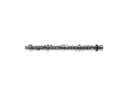
- Q: What tools are required to replace the camshaft for RPOs LY6/L76/L92 on Cadillac Escalade EXT?A:An engineer needs en 46330 timing belt tensioner retaining pin (EN 46330) and j 42386-a Flywheel holding tool (J 42386-A) and j 45059 angle meter (J 45059) to replace rpos ly6/l76/l92 camshafts. The replacement requires these specific tools: en 46330 timing belt tensioner retaining pin (EN 46330), j 42386-a Flywheel holding tool (J 42386-A), and j 45059 angle meter (J 45059). Begin the process by taking away the radiator support followed by the valve lifters and engine front cover and Starter motor. Install the j 42386-a meshed with the Flywheel teeth before applying one m10-1.5 x 120 mm and one m10-1.5 x 45 mm bolt which require a 50 n.m (37 lb ft) torque setting. Align the crankshaft sprocket with Camshaft position (CMP) actuator alignment mark and crankshaft sprocket alignment mark by rotating the crankshaft sprocket. Start by removing the cmp actuator solenoid valve (234) while you remove both the cmp actuator (235) and Timing Chain (208). When removing the Camshaft retainer bolts (204) together with retainer (203) approach the Camshaft bearings with extreme caution to prevent damage. Drop the Camshaft sprocket bolt into the front bolt hole to use it as an aid during Camshaft removal from the engine block. Use a bolt to handle the Camshaft while you apply clean engine oil to both Camshaft journals and bearings before reinstallation. Use a clean engine block gasket surface before putting the Camshaft retainer (203) with bolts (204) in place and tightening hex head bolts first to 25 n.m (18 lb ft) and torx(R) head bolts second to 15 n.m (11 lb ft). Install en 46330 by compressing its Timing Chain tensioner guide. Place the cmp actuator correctly onto the Camshaft locating pin where the sprocket teeth connect with Timing Chain teeth while maintaining the sprocket alignment marks in the correct position. Install cmp actuator (235) and Timing Chain (208) at the appropriate positioning where the locating pin receives proper alignment. Regular inspection must confirm the Timing Chain stays within the engine block's front face boundary. Fasten a brand-new cmp actuator solenoid valve (234) by hand to its appropriate torque. Check that the sprockets show correct alignment before taking out the en 46330. Crank the cmp actuator solenoid valve to 65 n.m torque (48 lb ft) then continue with a 90 degree torque final pass using j 45059. Before reassembly of the vehicle replace both the j 42386-a and its bolts and put back the Starter motor along with the engine front cover and valve lifters and radiator support.


