Make sure this part fits

GM 26075603
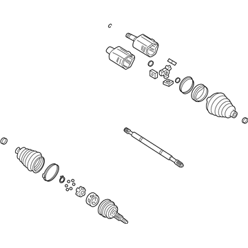
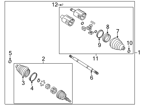
Axle Assembly, Front

2000-2007 GM

Customer Questions & Expert Answers (5)
GM 26075603 Axle Assembly, Front
  • Part Description
    Shaft Kit, Front Wheel Drive; CV Axle Assembly; Axle Shaft; CV Axle
  • Position
    Front
  • Replaced By
    20984613
  • Manufacturer
    General Motors
  • Manufacturer's Notes
    This part is discontinued.
Make sure this part fits
  • Vehicle Fitment

    Year Make Model Trim Engine
    2006-2007 Buick LucerneCXL, CXS8 Cyl 4.6 L GAS
    2000-2004 Cadillac DeVilleBase, DHS, DTS, Protection Series8 Cyl 4.6 L GAS
    2000-2004 Cadillac SevilleSLS, STS8 Cyl 4.6 L GAS
    2004 Pontiac BonnevilleGXP8 Cyl 4.6 L GAS
    Warning: California's Proposition 65
  • Customer Questions & Expert Answers

    Q:
    Can you help me check if this 26075603 is the right part for my car? Posted by ChevyPartsGiant Specialist
    A:
    Please Select Your Vehicle model to see if part number 26075603 is suitable before ordering.
    Posted by ChevyPartsGiant Specialist
    Q:
    What tools are required to service and repair the axle shaft assembly for front wheel drive shaft replacement (FE7) on Cadillac DeVille? Posted by Customer
    A:
    For the following requirements of servicing and repair of the Axle Shaft assembly, namely, front Axle Shaft change (FE7), the following tools are required: slide hammer (J 2619-O1), extension (J 29794), Axle Shaft remover (J 33008-A), hub spindle remover (J 42129). Start by lifting and supporting the vehicle, and discard away the tire and the wheel assembly. In case, there is an automatic level control, remove the automatic level sensor link from the ball stud located on the lower Control Arm. Next, pull off the outer Tie Rod End from the Steering Knuckle without turning the Tie Rod End jam nut. Bore a drift or punch into the brake rotor against the brake caliper to keep the Wheel Hub and bearing from turning. It is very important to change the front axle nut to a new one when it has been tampered with. Remove and dispose of the Axle Shaft Spindle Nut that maintains the relationship between the Axle Shaft and the hub, then remove the stabilizer shaft link. After disconnecting electrical connector from sensor repositioned the wheel speed sensor wiring harness far from the Ball Joint. Unplug the electrical connector from the wheel speed sensor and reposition the wiring harness and unplug the lower Ball Joint from the Steering Knuckle. Attach the hub spindle remover (J 42129) to the Wheel Hub and tighten it using wheel nuts, which keep the Axle Shaft until removed completely. Disengage the Axle Shaft from the Wheel Hub and bearing using the hub spindle remover (J 42129) while supporting the Axle Shaft. Combine the slide hammer (J 2619-O1), extension (J 29794), and Axle Shaft remover (J 33008-A) to ensure that the Axle Shaft lifts away from the transaxle and that it is removed from the car. For installation, install Axle Shaft into the transaxle and make sure that it is properly engaged by pulling outward on the inner tripot housing. Mount the Axle Shaft to the hub and bearing, join the Ball Joint to the Steering Knuckle, and the wheel speed sensor electrical connector. Mount the stabilizer shaft link then, get a drift/punch and jam it into the rotor versus the caliper, to keep the hub from rotating on its bearing. Clean and add a small bead of loctite dri-loc 201 (GM P/N 12345493) or equivalent to the entire length of the male thread on the drive axle prior to installation of the new front axle nut and then tighten it to 230 nm (170 ft. Lbs.). Finally connect the outer Tie Rod End to the Steering Knuckle, reconnect the automatic level sensor link if present and install the tire and wheel assembly and lower the vehicle.
    Posted by ChevyPartsGiant Specialist
    Q:
    How to replace the wheel axle shaft on Cadillac Seville? Posted by Customer
    A:
    The first step to replace a wheel drive shaft requires vehicle support while lifting it up then removing all tire and wheel components. When the vehicle uses road sensing suspension technology it requires users to disconnect the level sensor link which attaches to the ball stud located on the lower Control Arm. Disconnection of the outer Tie Rod End from the Steering Knuckle happens without touching the Tie Rod End jam nut. A drift or punch should be inserted through the brake rotor in front of the brake caliper to stop the Wheel Hub and bearing from rotating. A new Spindle Nut is needed whenever you remove the wheel drive shaft Spindle Nut because it should not be reutilized. Separate the stabilizer shaft link and disconnect the electrical connector from the Wheel Speed Sensor while placing the wiring harness in a safe position that avoids the Ball Joint. Use the Wheel Hub remover (J 42129) to fit the Wheel Hub and fasten it using wheel nuts until the wheel drive shaft becomes completely detached while continuously supporting the shaft. The Wheel Hub remover (J 42129) should be used to separate the wheel drive shaft from the Wheel Hub and bearing before assembling a combination of slide hammer (J2619-O1) with Axle Shaft remover extension (J 29794) along with Axle Shaft puller (J 33008-A) to extract the wheel drive shaft from the transaxle and remove it from the vehicle. To install the wheel drive shaft, position it into the transaxle and check its alignment through inner tripot housing outward pull. First insert the wheel drive shaft into the hub with bearing before linking the Ball Joint to the Steering Knuckle followed by restoring the Wheel Speed Sensor electrical connection. The link of the stabilizer shaft must be installed before using a drift or punch tool to stop the hub and bearing from rotating against the caliper. Fasten the new wheel drive shaft Spindle Nut by torquing it to 160 nm (118 lb ft). Complete the process by connecting the outer Tie Rod End to the Steering Knuckle then reattaching the level sensor link (on road sensing suspension vehicles) after installing the tire and wheel assembly and lowering the vehicle.
    Posted by ChevyPartsGiant Specialist
    Q:
    How to replace the wheel axle shaft on Cadillac DeVille? Posted by Customer
    A:
    Beginning the Axle Shaft replacement process involves vehicle lift and support followed by removal of the tire and wheel assembly. Vehicle owners should disconnect the automatic level sensor link from its ball stud position on the lower Control Arm. You should disconnect the outer Tie Rod End from the Steering Knuckle but should not tighten or loosen the Tie Rod End jam nut. Place a drift or punch inside the brake rotor alongside the brake caliper to stop Wheel Hub and bearing rotation. You must first disconnect the Axle Shaft Spindle Nut which holds the Axle Shaft to the hub before you can remove the stabilizer shaft link. You should move the Wheel Speed Sensor wiring harness to a location separate from the Ball Joint during the time you disconnect the electrical connector from the sensor. Users should begin by disconnecting the Wheel Speed Sensor electric connector and then move the wiring harness out of the Ball Joint path before separating the Ball Joint from the Steering Knuckle. Use of the hub spindle remover (J 42129) will require wheel nuts to hold the Wheel Hub in place while the Axle Shaft remains supported until complete vehicle removal. Insert the hub spindle remover (J 42129) into the Wheel Hub to unlock the Axle Shaft from the bearing and Wheel Hub while maintaining structural support onto the Axle Shaft. Use the slide hammer (J 2619-01), extension (J 29794), and Axle Shaft remover (J 33008-A) to remove the Axle Shaft from the transaxle as well as the vehicle. During installation insert the Axle Shaft into the transaxle to check Axle Shaft alignment by pulling outward on the inner tripot housing. First install the Axle Shaft to the hub and bearing and then connect the Ball Joint to the Steering Knuckle and the Wheel Speed Sensor electrical connector. After adding the stabilizer shaft link position a drift or punch through the rotor to block the hub and bearing from rotating. Use a torque wrench to tighten the Axle Shaft Spindle Nut against the Axle Shaft until it produces 160 nm (118 ft. Lbs.). Connect the outer Tie Rod End to the Steering Knuckle before reattaching the automatic level sensor link if present. Then install the tire and wheel assembly and lower the vehicle.
    Posted by ChevyPartsGiant Specialist
    Q:
    How do you connect and tighten the ball joint for the 2000 Cadillac DeVille? Posted by Customer
    A:
    Connect the ball joint to the knuckle, tighten the ball joint nut to 10 Nm (88 inch lbs.), followed by an additional 150 degrees while achieving a torque of 55 Nm (41 ft. lbs.).
    Posted by ChevyPartsGiant Specialist
    See expert answers on similar Axle Shaft
    If you have any questions about this product, please don't hesitate to ask us. We will be happy to help you!

OEM GM Axle Assembly, Front 26075603 Designed for Proper Fit and Performance

Original OEM GM parts deliver superior quality and meet all performance standards needed for optimal automotive operation. The authentic part identified by 26075603 Axle Assembly, Front is available in the market under the name GM Axle Shaft, Drive Shaft. This genuine product has a full warranty coverage from the manufacturer available at all authorized GM dealers throughout the United States. This part 26075603 Axle Assembly, Front fits certain Cadillac DeVille, Seville models, as well as Buick Lucerne. Additionally, it is compatible with Pontiac Bonneville models.
The original GM component designated by manufacturer part number 26075603 maintains top performance when functioning as the Shaft Kit, Front Wheel Drive; CV Axle Assembly; Axle Shaft; CV Axle unit at its Front. The component 26075603 is constructed from durable material and its dimensions span 30.2 x 5.8 x 5.7 inches while weighing 15.90 Pounds. The component is ready in New condition to ensure full compatibility with your vehicle system. This component receives the designation of Axle. The part 26075603 has available replacement options listed under 20984613. GM manufacturer provides a warranty that ensures reliable operation of this product. The Shipping Policy and Return Policy pages outline complete details regarding shipping procedures and return processes.
If you want to save money in the long run on maintenance and repairs, you should choose OEM products because they're of the top level of durability. Are you on the quest of finding GM parts, our site is worth a visit. We stock an endless selection of high-quality GM components including things like ignition coils all the way through to fan shrouds and all at prices that can not be matched. You have nothing to worry about because all our OEM parts are covered with a manufacturer warranty, which guarantees superior quality and value.