ChevyParts
My Garage
My Account
Cart
OEM 2005 Cadillac XLR Front Cross-Member
Front Engine Cross Member- Select Vehicle by Model
- Select Vehicle by VIN
Select Vehicle by Model
orMake
Model
Year
Select Vehicle by VIN
For the most accurate results, select vehicle by your VIN (Vehicle Identification Number).
1 Front Cross-Member found

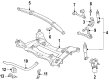
2005 Cadillac XLR Engine Cradle Part Number: 20850582
$251.99 MSRP: $376.74You Save: $124.75 (34%)Product Specifications- Other Name: Crossmember; Crossmember, Front Frame Cross Member
- Position: Front
- Replaces: 15864492, 15215882
- Item Weight: 38.20 Pounds
- Item Dimensions: 37.8 x 24.7 x 10.2 inches
- Condition: New
- Fitment Type: Direct Replacement
- SKU: 20850582
- Warranty: This genuine part is guaranteed by GM's factory warranty.
2005 Cadillac XLR Front Cross-Member
With a comprehensive array of OEM 2005 Cadillac XLR Front Cross-Member, from fuel pumps to door handles, our website is a one-stop-shop for your needs. All our genuine 2005 Cadillac XLR Front Cross-Member are backed by the manufacturer's warranty and are offered at competitive prices in the market. Rest assured, you can shop with complete confidence.
2005 Cadillac XLR Front Cross-Member Parts and Q&A
- Q: How to replace the Front Cross-Member on 2005 Cadillac XLR?A: To replace the front suspension crossmember, one can start by supporting it using engine support fixture (J38853-B). Lift and hold the vehicle, and remove the tire and wheel assemblies. Next, discharge the steering linkage outer Tie Rod End stud nuts and disconnect the electronic suspension control (ESC) sensor links. Take out the stabilizer shaft of the vehicle and take away the intermediate shaft lower coupling being connected to the steering gear. Disconnect the bolts from the electronic brake control module (EBCM)/brake pressure modulator valve (BPMV) bracket and hold up and move the ebcm/bpmv and bracket clear of the crossmember. Break the power steering gear mounting bolts and the power steering fluid cooler from the crossmember. Raise the power steering gear from the crossmember and hold it. Extract the transverse spring from a motor vehicle by using: transverse spring compressor (J 33432-A). Release the lower Shock Absorber from the lower control arms, and withdraw the lower Control Arm bolts from the crossmember. Place transmission jack under crossmember, be sure to remove the Engine Mount lower nuts. Remove the wheel speed sensor wiring harness, the electrical harness from the clips and also the brake pipe from clips on the crossmember. Remove the crossmember mounting nuts and take down the crossmember from the vehicle. During installation, elevate the crossmember to the vehicle so that the dowel pins are aligned to the frame rails and the Engine Mount studs. Replace new cross member mounting nuts and tighten up to 110 n.m (81 lb ft). Attach the Engine Mount lower nuts, secure the wheel speed sensor wiring harness retainer clips, and plug in the electrical harness into its clips along the cross member. Attach the brake pipe to the clips, and install the transverse spring with the j 33432-a attached to the crossmember. Mount the lower Control Arm and the shock absorbers to the lower control arms, and tighten Shock Absorber lower mounting nuts to 28 n.m (21 lb ft). Mount the crossmember by bolting the power steering to the crossmember, and tightening the mounting bolts to 100 n.m (74 lb ft), then install the bolts to the bpmv bracket. Connect intermediate shaft to the steering gear, install steering linkage outer tie rod ends to the steering knuckles, and reconnect esc sensor links. Finally, install stabilizer shaft, tire and wheel assemblies, lower vehicle, uninstall engine support fixture and conduct a vehicle front end alignment.
Related 2005 Cadillac XLR Parts
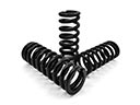 2005 Cadillac XLR Coil Springs
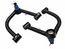 2005 Cadillac XLR Control Arm
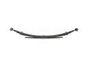 2005 Cadillac XLR Leaf Spring
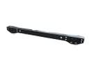 2005 Cadillac XLR Rear Crossmember
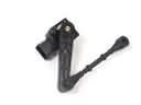 2005 Cadillac XLR Ride Height Sensor
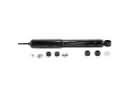 2005 Cadillac XLR Shock Absorber
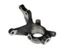 2005 Cadillac XLR Steering Knuckle
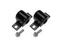 2005 Cadillac XLR Sway Bar Bushing
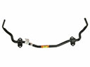 2005 Cadillac XLR Sway Bar Kit
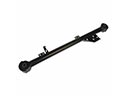 2005 Cadillac XLR Trailing Arm
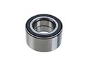 2005 Cadillac XLR Wheel Bearing
 2005 Cadillac XLR Wheel Hub