ChevyParts
My Garage
My Account
Cart
OEM Cadillac XLR Front Cross-Member
Front Engine Cross Member- Select Vehicle by Model
- Select Vehicle by VIN
Select Vehicle by Model
orMake
Model
Year
Select Vehicle by VIN
For the most accurate results, select vehicle by your VIN (Vehicle Identification Number).
1 Front Cross-Member found

Cadillac XLR Engine Cradle Part Number: 20850582
$251.99 MSRP: $376.74You Save: $124.75 (34%)
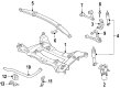
Cadillac XLR Front Cross-Member
Want to cut long-term maintenance and repair costs? Choose OEM Front Cross-Member. Those parts deliver top durability you can trust. On our site, you'll find a huge catalog of genuine Cadillac XLR parts. Prices are unbeatable, so you can keep more in your pocket. Every OEM Cadillac XLR Front Cross-Member includes a manufacturer's warranty. You can also get an easy return policy that keeps buying risk free. Fast delivery, get your car on the road quickly. It's simple to search, compare, and order. Stop guessing about quality or fit. Order today and save with parts that last.
As a core structural element of the Cadillac XLR Front Cross-Member represents the reliability characteristics which make the Cadillac XLR roadster known for its outstanding engineering capabilities. The Front Cross-Member functions as a critical support structure to stabilize both engine and transmission units thereby improving operational safety. The Cadillac XLR Front Cross-Member uses unique steel metal construction that combines a distinctive boxed structure to handle major loads which provides peak body panel alignment and handling performance. The Front Cross-Member stands as a vital element for preserving Cadillac XLR performance from 2003 through 2009. The Front Cross-Member's The section shape found in the cross-member adds exceptional torsional strength while enabling superior resistance to deflection strengthening its position in the chassis frame design. The component works with multiple Cadillac XLR vehicle models to enhance vehicle structure and operational effectiveness. The Cadillac XLR Front Cross-Member operates as a safety enhancement because it creates a secure foundation which enables Magnetic Ride Control and pushes the power of the V8 Northstar engine. This critical component enhances the the automaker model Front Cross-Member position in the automotive field through its superior high-performance abilities and balanced weight distribution characteristics which protect the car's dual status as luxury icon and performance superior.
Cadillac XLR Front Cross-Member Parts Questions & Experts Answers
- Q: How to replace the Front Cross-Member on Cadillac XLR?A:To replace the front suspension crossmember, one can start by supporting it using engine support fixture (J38853-B). Lift and hold the vehicle, and remove the tire and wheel assemblies. Next, discharge the steering linkage outer Tie Rod End stud nuts and disconnect the electronic suspension control (ESC) sensor links. Take out the stabilizer shaft of the vehicle and take away the intermediate shaft lower coupling being connected to the steering gear. Disconnect the bolts from the electronic brake control module (EBCM)/brake pressure modulator valve (BPMV) bracket and hold up and move the ebcm/bpmv and bracket clear of the crossmember. Break the power steering gear mounting bolts and the power steering fluid cooler from the crossmember. Raise the power steering gear from the crossmember and hold it. Extract the transverse spring from a motor vehicle by using: transverse spring compressor (J 33432-A). Release the lower Shock Absorber from the lower Control Arms, and withdraw the lower Control Arm bolts from the crossmember. Place transmission jack under crossmember, be sure to remove the Engine Mount lower nuts. Remove the wheel speed sensor wiring harness, the electrical harness from the clips and also the brake pipe from clips on the crossmember. Remove the crossmember mounting nuts and take down the crossmember from the vehicle. During installation, elevate the crossmember to the vehicle so that the dowel pins are aligned to the frame rails and the Engine Mount studs. Replace new cross member mounting nuts and tighten up to 110 n.m (81 lb ft). Attach the Engine Mount lower nuts, secure the wheel speed sensor wiring harness retainer clips, and plug in the electrical harness into its clips along the cross member. Attach the brake pipe to the clips, and install the transverse spring with the j 33432-a attached to the crossmember. Mount the lower Control Arm and the shock absorbers to the lower control arms, and tighten Shock Absorber lower mounting nuts to 28 n.m (21 lb ft). Mount the crossmember by bolting the power steering to the crossmember, and tightening the mounting bolts to 100 n.m (74 lb ft), then install the bolts to the bpmv bracket. Connect intermediate shaft to the steering gear, install steering linkage outer tie rod ends to the Steering Knuckles, and reconnect esc sensor links. Finally, install stabilizer shaft, tire and wheel assemblies, lower vehicle, uninstall engine support fixture and conduct a vehicle front end alignment.

Related Cadillac XLR Parts
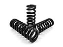 Cadillac XLR Coil Springs
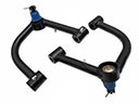 Cadillac XLR Control Arm
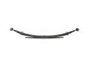 Cadillac XLR Leaf Spring
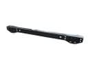 Cadillac XLR Rear Crossmember
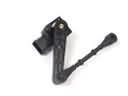 Cadillac XLR Ride Height Sensor
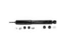 Cadillac XLR Shock Absorber
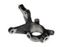 Cadillac XLR Steering Knuckle
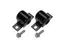 Cadillac XLR Sway Bar Bushing
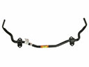 Cadillac XLR Sway Bar Kit
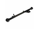 Cadillac XLR Trailing Arm
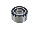 Cadillac XLR Wheel Bearing
 Cadillac XLR Wheel Hub