ChevyParts
My Garage
My Account
Cart
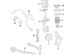
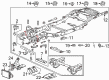
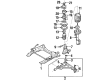
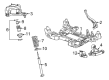
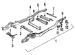
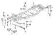
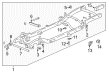
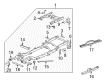
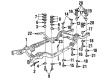
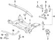
OEM Cadillac Front Cross-Member
Front Engine Cross Member- Select Vehicle by Model
- Select Vehicle by VIN
Select Vehicle by Model
orMake
Model
Year
Select Vehicle by VIN
For the most accurate results, select vehicle by your VIN (Vehicle Identification Number).
16 Front Cross-Members found

Cadillac Crossmember Part Number: 23325368
$670.41 MSRP: $1006.82You Save: $336.41 (34%)Ships in 1-3 Business DaysProduct Specifications- Other Name: Cradle, Chassis
- Position: Front

Cadillac Front Crossmember Part Number: 22833941
$203.81 MSRP: $304.71You Save: $100.90 (34%)Ships in 1-3 Business DaysProduct Specifications- Other Name: Crossmember; Crossmember, Front Frame Cross Member
- Position: Front
- Replaces: 15201007, 15716565

Cadillac Suspension Crossmember, Front Part Number: 22833303
$182.87 MSRP: $273.40You Save: $90.53 (34%)Ships in 1-2 Business DaysProduct Specifications- Other Name: Crossmember Assembly-Drivetrain & Front Suspension Front; Transfer Case Mount; Transmission Mount; Engine Crossmember; Trans Crossmember; Crossmember, Frame Bell Housing(Attaches To Frame And Side Rails)
- Position: Front
- Replaces: 19150105
Cadillac Engine Cradle Part Number: 9127270
Product Specifications- Other Name: Frame, Drivetrain & Front Suspension
- Position: Front

Cadillac Engine Cradle, Front Part Number: 25767292
Product Specifications- Other Name: Frame, Drivetrain & Front Suspension
- Position: Front
- Replaced by: 25767291

Cadillac Transmission Support Part Number: 15735499
Product Specifications- Other Name: Crossmember, Transmission Mounting; Crossmember
- Replaces: 12388903
Cadillac Transmission Support Part Number: 15732251
Product Specifications- Other Name: Crossmember, Transmission Mounting
- Replaces: 15988465
Cadillac Transmission Support Part Number: 15732249
Product Specifications- Other Name: Crossmember, Transmission Mounting; Support, Transmission Mounting
Cadillac Transmission Support Part Number: 15726594
Product Specifications- Other Name: Crossmember, Transmission Mounting

Cadillac Trans Crossmember Part Number: 15201164
Product Specifications- Other Name: Crossmember, Transmission Mounting; Transfer Case Mount; Transmission Mount

Cadillac Support Brace Part Number: 15050470
Product Specifications- Other Name: Crossmember, Frame Cross, Intermediate (Transmission Support Cross Member); Crossmember, Intermediate(Transmission Support Cross Member)
- Position: Front

Cadillac Support Brace Part Number: 12479997
Product Specifications- Other Name: Crossmember, Frame Cross, Intermediate (Transmission Support Cross Member); Crossmember, Intermediate(Transmission Support Cross Member)
- Position: Front
Cadillac Crossmember Part Number: 15981867
Product Specifications- Other Name: Member-Front; Crossmember, Intermediate(Transmission Support Cross Member)

Cadillac Support Brace, Rear Inner Driver Side Part Number: 14008433
Product Specifications- Other Name: Brace, Rear Quarter Inner; Front Subframe Brace; Frame Assembly Brace; Front Unit Brace; Front Frame Cross Member Brace
- Position: Rear Inner Driver Side

Cadillac Engine Cradle Part Number: 20850582
$251.99 MSRP: $376.74You Save: $124.75 (34%)Product Specifications- Other Name: Crossmember; Crossmember, Front Frame Cross Member
- Position: Front
- Replaces: 15864492, 15215882
Cadillac Trans Crossmember Part Number: 10398965
$41.89 MSRP: $65.61You Save: $23.72 (37%)Product Specifications- Other Name: Crossmember, Transmission Mounting; Transfer Case Mount; Transmission Mount
Cadillac Front Cross-Member Parts Questions & Experts Answers
- Q: How to replace the Front Cross-Member on Cadillac Catera?A: To replace the front suspension cross member, start by attaching the engine support fixture (J28467-A) at the lift points and lifting the vehicle without dropping it on the ground. Ensure that the vehicle tipping is firmly held. Univolt the front wheel assemblies, wheel speed sensors, brake wear indicator wires, brake flex hose clips, and hoses off the strut assemblies. Remove the brake caliper assembly bolts from the steering knuckles and support the caliper assemblies in order to avoid damaging them. Then, take out the outer tie rod nuts and use the tie rod/wheel stud puller (J6627-A) in order to pull the outer tie rod ball studs away from the steering knuckles. Remove the pinch bolts on the lower control arm ball stud and the steering knuckles from the lower control arm ball studs, remove the stabilizer shaft link nuts and the links as well. Subsequently, unbolt the engine mount and support the crossmember frame and then unbolt the engine front crossmember frame bolts and lower the frame. For installation, place the front crossmember frame and use new engine front crossmember frame bolts and tighten them such that use of torque/angle meter (J36660-A) value of set torque is achieved. Install the engine mount nuts, stabilizer shaft links, and their nuts adjusting them appropriately. Reattach steering knuckles to the lower control arm ball studs using new pinch bolts and attach the outer tie rods using the linkage installer (J42089) to tighten the tie rod ball studs. Apply new self-locking outer tie rod nuts, and check that the brake caliper assembly is cleaned and coated with locking compound at the time of reassembling the caliper assemblies with the torque/angle meter (J36660-A). Lastly, reconnect the wiring for Wheel Speed Sensor and brake wear indicator wires, brake hoses, and wheel speed sensors, tighten the Wheel Speed Sensor bolts, reinstall the front wheeal assemblies, lower the vehicle, and align the wheels.
- Q: How to Properly Handle the Front Cross-Member Replacement Process on Cadillac XLR?A: To replace the front suspension crossmember, start with the engine being supported by the engine support fixture (J41158-B) and the vehicle being raised. Be aware that new tire and wheel sets may have designated 'left' and 'right' sides. For the previous car, the outermost part on the right side was removed first, and during installation, the opposite order was followed. Undo the stabilizer shaft, detaching the intermediate shaft lower coupling from the steering gear, and, as well as the bolts from the electronic brake control module (EBCM)/brake pressure modulator valve (BPMV) bracket. Support the ebcm/bpmv and bracket away from the crossmember, then remove the bolts from the power steering gear and the power steering fluid cooler, and remove them from the crossmember. Lift the power steering gear up off of the cross-member and support it. The transverse spring compressor (J 33432-A) must be applied to remove the transverse spring from the vehicle by the lifting of this spring. However, the lower Shock Absorber bolts must then be disconnected from the lower control arms; this in turn requires the removal of the lower Control Arm bolts from this arm's position into the position of the crossmember. Jack up the vehicle by keeping the transmission jack under the crossmember, then remove the lower nuts of the mount under the engine, disconnect the wiring harness of the wheel speed from the panel, disconnect the electrical harness from the clips, and the clips themselves at the crossmember from the brake pipe. Disassemble the crossmember mounting nuts and bring the crossmember down through the vehicle. For installation put the crossmember up to the vehicle and align the dowel pins to the frame rails and the engine mount studs and use new crossmember mounting nuts tighten up to 110 n.m (81 lb ft). Install engine mount lower nuts, secure the wheel speed sensor wiring harness to the retaining clips, the brake pipe on the retaining clips, and the electrical harness on the clips of the crossmember. Install the transverse spring with the aid of the transverse spring compressor (J 33432-A) attached, then install the lower Control Arm as well as the shock absorbers to the lower control arms with the aid of tightening the nuts that hold the bottom of the Shock Absorber with 28 n.m (21 lb ft). Mount the power steering gear to the cross member, fastening the mounting bolts to 100 n.m (74 lb ft), followed by the bolts to the bpmv bracket, and linking the intermediate shaft to the steering gear, and mounting the steering linkage outer tie rods to the steering knuckles. Lastly, connect esc sensor links place the stabilizer shaft, re-mount the tire and wheel assemblies, lower the vehicle and remove the engine support fixture, conduct the vehicle front-end alignment.

Related Cadillac Parts
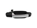 Cadillac Door Handle
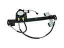 Cadillac Window Regulator
 Cadillac Control Arm Bumper
 Cadillac Door Check
 Cadillac Door Striker
 Cadillac Floor Pan
 Cadillac Lift Support
 Cadillac Side View Mirrors
 Cadillac Sunroof Cable
 Cadillac Tailgate Latch
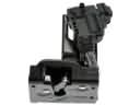 Cadillac Tailgate Lock Actuator Motor
 Cadillac Window Channel