ChevyParts
My Garage
My Account
Cart
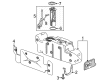
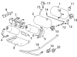
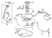
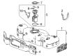
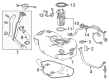
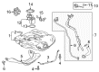
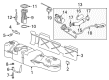
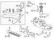
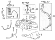
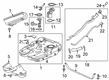
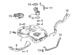
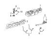
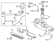
OEM Chevrolet Fuel Tank
Gas Tank- Select Vehicle by Model
- Select Vehicle by VIN
Select Vehicle by Model
orMake
Model
Year
Select Vehicle by VIN
For the most accurate results, select vehicle by your VIN (Vehicle Identification Number).
286 Fuel Tanks found

Chevrolet Fuel Tank Part Number: 84637953
$114.52 MSRP: $171.17You Save: $56.65 (34%)Ships in 1-3 Business DaysProduct Specifications- Other Name: Tank Assembly-Fuel (W/Sender); Tank, Fuel
- Replaced by: 84878510

Chevrolet Fuel Tank Part Number: 23389920
$2370.62 MSRP: $3746.83You Save: $1376.21 (37%)Ships in 1-3 Business DaysProduct Specifications- Other Name: Tank, Fuel
- Replaces: 19258093

Chevrolet Fuel Tank Part Number: 23389918
$2902.21 MSRP: $4587.02You Save: $1684.81 (37%)Ships in 1-3 Business DaysProduct Specifications- Other Name: Tank, Fuel
- Replaces: 19258379

Chevrolet Fuel Tank Part Number: 19352362
$2195.12 MSRP: $3469.44You Save: $1274.32 (37%)Ships in 1-3 Business DaysProduct Specifications- Other Name: Tank Assembly, CNG; Tank, Fuel
- Replaces: 19258363

Chevrolet Fuel Tank Part Number: 95102145
$153.04 MSRP: $228.77You Save: $75.73 (34%)Ships in 1-3 Business DaysProduct Specifications- Other Name: Tank, Fuel
- Replaces: 95051129

Chevrolet Fuel Tank Part Number: 85112832
$765.01 MSRP: $1148.69You Save: $383.68 (34%)Ships in 1-3 Business DaysProduct Specifications- Other Name: Tank, Fuel
- Replaced by: 85563732

Chevrolet Fuel Tank Part Number: 42622694
$141.16 MSRP: $211.02You Save: $69.86 (34%)Ships in 1-3 Business DaysProduct Specifications- Other Name: Tank, Fuel
Chevrolet Fuel Tank Part Number: 12382992
$276.75 MSRP: $413.68You Save: $136.93 (34%)Ships in 1-3 Business DaysProduct Specifications- Other Name: Tank Assembly, Fuel; Tank

Chevrolet Fuel Tank Part Number: 84574976
$244.63 MSRP: $365.67You Save: $121.04 (34%)Ships in 1-3 Business DaysProduct Specifications- Other Name: Tank Kit, Fuel
- Replaces: 23150673, 23406966
Chevrolet Fuel Tank Part Number: 85538364
$1468.43 MSRP: $2204.85You Save: $736.42 (34%)Ships in 1-3 Business DaysProduct Specifications- Other Name: Tank, Fuel
- Replaces: 84515282

Chevrolet Fuel Tank Part Number: 23360477
$881.33 MSRP: $1323.32You Save: $441.99 (34%)Ships in 1-3 Business DaysProduct Specifications- Other Name: Tank, Fuel
- Replaces: 25901671

Chevrolet Fuel Tank Part Number: 95367339
$919.80 MSRP: $1381.07You Save: $461.27 (34%)Product Specifications- Other Name: Tank, Fuel
- Replaces: 95297328, 95080131

Chevrolet Fuel Tank Part Number: 85633466
$914.44 MSRP: $1373.03You Save: $458.59 (34%)Ships in 1-2 Business DaysProduct Specifications- Other Name: Tank, Fuel
- Replaced by: 85743893
- Replaces: 84724303, 84740715, 84865847, 84867689, 85138841, 84900158, 85138842

Chevrolet Fuel Tank Part Number: 85531335
$675.12 MSRP: $1013.70You Save: $338.58 (34%)Ships in 1-2 Business DaysProduct Specifications- Other Name: Tank, Fuel
- Replaces: 84820665

Chevrolet Fuel Tank Part Number: 84009042
$716.87 MSRP: $1076.39You Save: $359.52 (34%)Product Specifications- Other Name: Tank, Fuel
- Replaces: 20935353, 23315309, 15826971
Chevrolet Fuel Tank Part Number: 23406969
$262.86 MSRP: $392.92You Save: $130.06 (34%)Ships in 1-3 Business DaysProduct Specifications- Other Name: Tank Kit, Fuel
- Replaced by: 84507510
Chevrolet Fuel Pump Part Number: 87848344
$2312.13 MSRP: $3471.64You Save: $1159.51 (34%)Product Specifications- Other Name: Tank, Fuel; Fuel Tank
- Replaces: 19122202, 84082482, 84277467, 20969743

Chevrolet Fuel Tank Part Number: 84164752
Product Specifications- Other Name: Tank, Fuel
- Replaces: 84009046

Chevrolet Fuel Tank Part Number: 84055540
Product Specifications- Other Name: Tank, Fuel
- Replaces: 19258364

Chevrolet Fuel Tank Part Number: 22990929
Product Specifications- Other Name: Tank, Fuel; Tank
| Page 1 of 15 |Next >
1-20 of 286 Results
Chevrolet Fuel Tank
Want to cut long-term maintenance and repair costs? Choose OEM Fuel Tank. Those parts deliver top durability you can trust. On our site, you'll find a huge catalog of genuine Chevrolet parts. Prices are unbeatable, so you can keep more in your pocket. Every OEM Chevrolet Fuel Tank includes a manufacturer's warranty. You can also get an easy return policy that keeps buying risk free. Fast delivery, get your car on the road quickly. It's simple to search, compare, and order. Stop guessing about quality or fit. Order today and save with parts that last.
Chevrolet Fuel Tank Parts Questions & Experts Answers
- Q: How to service the fuel level sensor in a plastic fuel tank on Chevrolet Cavalier?A:Service of the Fuel Level Sensor located in a plastic tank requires a step which involves following the fuel pressure relief procedure to drain fuel system pressure. Remove the Fuel Tank content before removing it from its place. Begin by removing the fuel sender assembly followed by a disconnection of the Fuel Pump and fuel level sender electrical retaining clip located at the upper part of the modular fuel sender assembly. Using the procedure completely disengage the Fuel Pump and fuel level sender electrical connector while pressing down on the 3 tabs that maintain the upper fuel reservoir in place relative to the lower reservoir to efficiently remove the upper reservoir. Rotate the tab on the Fuel Level Sensor and push the sensor upward through the housing. Take the retaining clip off the electrical connector to extract the fuel level sender wires which must be noted for their positions. When installing the wires ensure they pass underneath the fuel level sender and verify that the tab effectively attaches itself. Drop the Fuel Level Sensor down its housing before inserting the upper reservoir into the lower reservoir while locking the three tabs in position. Connect the two wires into the connector and fasten it with the retaining clip before linking the Fuel Pump and Fuel Level Sensor electrical connector through the retaining clip. The installation process requires you to restore the fuel sender assembly while putting back the Fuel Tank filling up the tank space and binding the fuel fill cap. Turn on the ignition while the engine remains off for two seconds before turning it off for another ten seconds. After this period, repeat the process by turning on the ignition once more with the engine still off and finally check for fuel leaks.
- Q: How to replace the fuel tank module on the left side on Chevrolet Corvette?A:The process of Fuel Tank module replacement on the left side begins by disconnecting the negative Battery Cable followed by removing the left Fuel Tank and placing it on a suitable work surface. Separate the Fuel Pump jumper harness from the module and disconnect both the jet line insert from the crossover tube at the Fuel Tank and remove the fuel feed line from its welded clip position. Pay attention since the Fuel Pump module possesses spring action which causes it to rise after the removal of the locking ring. The procedure requires removal of the locking ring from the Fuel Pump module with the fuel sender lock ring tool (J39765-A) so the technician can extract the fuel module while retaining both jet lines without harming the fuel sender float arm. Remove the jet lines from their quick-connect connectors installed at the Fuel Pump module inner port before extracting both lines from their retaining cup then removing the module o-ring through the Fuel Tank opening. The jet line insert should be removed through the crossover tube which leads to the Fuel Tank opening. To replace the fuel module assembly one should move the fuel level sender card from the old module into the new one. Place the new jet line insert through the crossover tube to the Fuel Tank opening and fasten it with the Fuel Pump module o-ring at the Fuel Tank opening. The jet line connector needs tape application to gain access while the pump module enters the Fuel Tank. Feed the new pump module into the Fuel Tank until it reaches the midpoint while cautioning against float arm damage. Then use the taped jet line to guide its upward movement through the pump module opening. Attach the jet line connectorless component into the module retainer cup while securing it with the module retaining clip. Pull the tape from the jet line by using a connector but observe that all connectors connect properly. You should attach the Fuel Pump module lock ring to the inner module port after connecting jet line quick-connect connectors. The fuel sender lock ring tool (J39765-A) must be used to achieve full ring engagement of the Fuel Pump module lock ring. Following this complete the fuel line connection into the weld clip at the tank's side. Check the resistance values of the Fuel Pump module using a dmm against empty and full Fuel Tank conditions by inverting the Fuel Tank to measure the readings (40 ohms resistance when empty, 250 ohms when full). Reinstall the left Fuel Tank while connecting the jet line insert connector into the crossover tube to the Fuel Tank opening and attaching the Fuel Pump jumper harness to the Fuel Pump module.
- Q: How to Service and Repair the Fuel Tank Unit on a Chevrolet Equinox?A:The replacement of the primary Fuel Tank module needs the j 45722 (Fuel Sender Lock Ring Wrench) along with safety precautions such as a shop cloth on loose fuel line fittings and an approved fuel collection container. All fuel pipe and hose connections need cleaning before taking apart while penetrating oil should be applied to the cam-lock ring tang of the Fuel Pump module. Acquire new sealing materials for the primary and secondary fuel tanks because these accessories are essential during servicing operations. Start your repair by taking off the secondary Fuel Pump module followed by unplugging the electrical connections from the primary Fuel Pump module together with the Fuel Tank pressure sensor. To prevent the damage of the lock ring use j 45722 only when cutting the plastic strap that surrounds the Fuel Tank. Never touch the fuel sender assembly near the fuel pipes to defend against joint damage while you should utilize a secure method of Fuel Tank attachment instead of using impact tools. The j 45722 tool operated by a breaker-bar will release the fuel sender lock ring through counter-clockwise rotation. Raising the pump module slightly will allow you to disengage the orientation tabs before rotating it 45 degrees in order to remove the primary Fuel Pump module assembly without bending the sending unit float arm. The Fuel Pump module-to-tank seal (O-ring) must always be replaced when removing it and you should discard the old seal. The procedure for removing the fuel level sending unit depends on the replacement plan. Then look at the lock ring for any damage as well as warpage; replace it if it exceeds 0.41 mm (0.016 in). To install the new primary Fuel Pump module assembly users must connect the fuel level sending unit to the new Fuel Pump before fitting the assembly with proper orientation tab alignment. The installation of the fuel sender seal requires proper placement with upward-facing orientation of both parts before tightening with j 45722 while rotating clockwise. Reinstall the Fuel Tank pressure sensor while connecting the wiring harness to the primary Fuel Pump module followed by installation of the secondary Fuel Pump module before reinstalling the Fuel Tank.


Related Chevrolet Parts
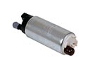 Chevrolet Fuel Pump
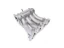 Chevrolet Intake Manifold
 Chevrolet Air Filter
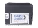 Chevrolet Cruise Control Module
 Chevrolet Air Hose
 Chevrolet Fuel Filler Housing
 Chevrolet Fuel Pressure Sensor
 Chevrolet Fuel Pump Gasket
 Chevrolet Fuel Tank Lock Ring
 Chevrolet Idle Control Valve
 Chevrolet Throttle Body Gasket
 Chevrolet Vapor Pressure Sensor
Browse Chevrolet Fuel Tank by Models
Nova S10 Colorado C10 Tahoe Cruze Malibu Camaro Equinox Impala SS SSR Avalanche Silverado 1500 Silverado 2500 HD Caprice Classic Cobalt Suburban Traverse Blazer HHR Sonic Tracker Volt El Camino K10 Spark Trax Trailblazer Astro Cavalier Corvette C20 Aveo Beretta C1500 C2500 C30 C3500 Celebrity City Express Corsica Express 1500 Express 2500 Express 3500 G10 G20 G30 K1500 K20 K2500 K30 K3500 K5 Blazer Lumina Metro Monte Carlo P30 S10 Blazer Silverado 2500 Sprint Uplander Venture Lumina APV Silverado 3500 Suburban 1500 Trailblazer EXT Avalanche 1500 Avalanche 2500 Aveo5 C10 Suburban C1500 Suburban C20 Suburban C2500 Suburban Captiva Sport Cruze Limited Impala Limited K10 Suburban K1500 Suburban K20 Suburban K2500 Suburban Malibu Limited P20 R10 R10 Suburban R1500 Suburban R20 R20 Suburban R2500 R2500 Suburban R30 R3500 Silverado 1500 Classic Silverado 1500 HD Silverado 1500 HD Classic Silverado 1500 LD Silverado 1500 LTD Silverado 2500 HD Classic Silverado 3500 Classic Silverado 3500 HD Spark EV Suburban 2500 Suburban 3500 HD V10 V10 Suburban V1500 Suburban V20 V20 Suburban V2500 Suburban V30 V3500