ChevyParts
My Garage
My Account
Cart
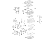
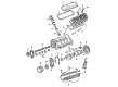
OEM GMC Camshaft
Cam- Select Vehicle by Model
- Select Vehicle by VIN
Select Vehicle by Model
orMake
Model
Year
Select Vehicle by VIN
For the most accurate results, select vehicle by your VIN (Vehicle Identification Number).
97 Camshafts found


GMC Camshaft Part Number: 12586532
$115.94 MSRP: $182.40You Save: $66.46 (37%)Product Specifications- Other Name: Camshaft, Engine


GMC Camshaft Part Number: 12672469
$127.46 MSRP: $216.96You Save: $89.50 (42%)Product Specifications- Other Name: Camshaft, Engine


GMC Camshaft Part Number: 12638172
$79.23 MSRP: $124.09You Save: $44.86 (37%)Ships in 1-3 Business DaysProduct Specifications- Other Name: Camshaft, Engine


GMC Camshaft Part Number: 10241691
$353.35 MSRP: $556.00You Save: $202.65 (37%)Ships in 1-3 Business DaysProduct Specifications- Other Name: Camshaft, Engine


GMC Camshaft Part Number: 12625439
$393.18 MSRP: $618.68You Save: $225.50 (37%)Product Specifications- Other Name: Camshaft, Engine
- Replaces: 12612274


GMC Camshaft Part Number: 12633773
$345.16 MSRP: $610.73You Save: $265.57 (44%)Ships in 1-2 Business DaysProduct Specifications- Other Name: Camshaft, Engine
- Replaced by: 19432226
GMC Camshaft Part Number: 12633925
$158.35 MSRP: $249.14You Save: $90.79 (37%)Ships in 1-3 Business DaysProduct Specifications- Other Name: Camshaft, Engine


GMC Camshaft Part Number: 12677832
$70.88 MSRP: $111.05You Save: $40.17 (37%)Ships in 1-3 Business DaysProduct Specifications- Other Name: Camshaft, Engine
- Replaces: 12647871
GMC Camshaft Part Number: 55501297
$91.01 MSRP: $142.53You Save: $51.52 (37%)Ships in 1-3 Business DaysProduct Specifications- Other Name: Camshaft, Engine

GMC Camshaft Part Number: 12569525
$93.79 MSRP: $124.20You Save: $30.41 (25%)Ships in 1-2 Business DaysProduct Specifications- Other Name: Camshaft, Engine
GMC Camshaft Part Number: 55511463
$320.79 MSRP: $504.53You Save: $183.74 (37%)Ships in 1-3 Business DaysProduct Specifications- Other Name: Camshaft Assembly-Intake; Camshaft, Engine
- Replaces: 55504558

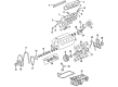
GMC Camshaft, Driver Side Part Number: 12638399
$94.44 MSRP: $147.98You Save: $53.54 (37%)Ships in 1-2 Business DaysProduct Specifications- Other Name: Camshaft Assembly-Exhaust (Left-Hand); Camshaft, Engine
- Position: Driver Side
- Replaces: 12638171
GMC Camshaft Part Number: 12677826
$76.44 MSRP: $119.74You Save: $43.30 (37%)Ships in 1-3 Business DaysProduct Specifications- Other Name: Camshaft Assembly-Intake; Camshaft, Engine
- Replaces: 12647875
GMC Camshaft Part Number: 40009063
$104.13 MSRP: $163.07You Save: $58.94 (37%)Ships in 1-3 Business DaysProduct Specifications- Other Name: Camshaft, Engine


GMC Camshaft Part Number: 12632270
$49.84 MSRP: $120.12You Save: $70.28 (59%)Ships in 1-3 Business DaysProduct Specifications- Other Name: Camshaft, Engine
GMC Camshaft Part Number: 55508605
$88.78 MSRP: $139.04You Save: $50.26 (37%)Ships in 1-3 Business DaysProduct Specifications- Other Name: Camshaft, Engine
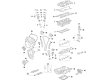
GMC Camshaft Part Number: 12711967
$396.90 MSRP: $681.66You Save: $284.76 (42%)Ships in 1-2 Business DaysProduct Specifications- Other Name: Camshaft Assembly, Overhead Valve; Camshaft, Engine
- Replaces: 12617373, 12623065

GMC Camshaft Part Number: 12565557
$141.09 MSRP: $193.15You Save: $52.06 (27%)Product Specifications- Other Name: Camshaft, Engine
GMC Camshaft Part Number: 12646602
$235.66 MSRP: $370.71You Save: $135.05 (37%)Ships in 1-3 Business DaysProduct Specifications- Other Name: Camshaft Assembly-Intake; Camshaft, Engine

GMC Camshaft Part Number: 12552296
$344.26 MSRP: $591.26You Save: $247.00 (42%)Ships in 1-3 Business DaysProduct Specifications- Other Name: Camshaft, Engine
| Page 1 of 5 |Next >
1-20 of 97 Results
GMC Camshaft
Want to cut long-term maintenance and repair costs? Choose OEM Camshaft. Those parts deliver top durability you can trust. On our site, you'll find a huge catalog of genuine GMC parts. Prices are unbeatable, so you can keep more in your pocket. Every OEM GMC Camshaft includes a manufacturer's warranty. You can also get an easy return policy that keeps buying risk free. Fast delivery, get your car on the road quickly. It's simple to search, compare, and order. Stop guessing about quality or fit. Order today and save with parts that last.
GMC Camshaft Parts Questions & Experts Answers
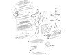
- Q: How to replace the right side camshaft on GMC Acadia?A:The right side Camshaft replacement process starts with manifold removal of the lower intake alongside Camshaft cover sensors and position actuator solenoid and Crankshaft balancer. Use the Crankshaft rotation socket (EN 46111) to rotate the Crankshaft which allows positioning the camshafts at a low tension neutral stage while the Camshaft flats maintain parallel alignment with the Camshaft cover rail. The engine needs stable structure by using an open-end wrench to halt the hex Camshaft movement despite keeping the Camshaft position actuator bolt in position. Use the Timing Chain retention tool (EN 46108) by completely inserting it to the Timing Chain then tighten its nuts firmly until marks appear on both the Camshaft Timing Chain and Camshaft position actuators while maintaining proper alignment for assembly. Mark the Timing Chain and corresponding positions on each Camshaft position actuator before removing both the Camshaft position actuator bolt and Camshaft bearing caps and Camshaft from the engine block. To install correctly position the alignment marks on both the Camshaft position actuators alongside the Timing Chain before you skip tightening the Camshaft position actuator bolt. Begin with Camshaft alignment at the Cylinder Head. Then proceed to install the Camshaft actuators before incorporating the camshafts and Camshaft bearing caps. Install the Crankshaft balancer before using the open-end wrench at the Camshaft hex to stop rotation of components. The maintenance work ends with the installation of Camshaft position actuators accompanied by the intake Camshaft position actuator solenoid and Camshaft sensors before Camshaft cover and lower Intake Manifold attachment.
- Q: How to replace the camshaft on GMC Canyon?A:You can begin Camshaft replacement by taking out the Camshaft cover together with the Camshaft position (CMP) sensor. Reverse Crankshaft rotation until the #1 Piston reaches its top dead center (TDC) position on the compression stroke. The delphi word on the exhaust Camshaft position actuator needs to become parallel to the cam cover mating surface of the Cylinder Head. You should install the Camshaft holding tool (J 44221) behind the camshafts before discarding both intake and exhaust Camshaft sprocket bolts. The installation of the Camshaft sprocket holding tool (J 44222) to the Cylinder Head front requires complete tightening of its two bolts while proper adjustment of the horizontal bolt into the exhaust Camshaft phaser actuator sprocket before sprocket removal from camshafts. Adjust the horizontal bolts into the Camshaft sprockets that are attached to the j 44222 tool which functions as a Cylinder Head sprocket holder to sustain chain tension. Transfer the sprocket with Timing Chain from each Camshaft to the Camshaft sprocket holding tool (J 44222). The mechanic should loosen the Camshaft cap bolts slightly to clear valve spring pressure before removing both caps and the Camshaft holding tool (J 44221) along with the camshafts from the Cylinder Head. Clean engine oil should be applied to the Camshaft journals thrust face and lobes before mounting the Camshaft holding tool (J 44221) with Camshaft flat positioned up against the #1 tdc position. After oiling the intake and exhaust camshafts plus their caps reconstruct them within the original positions by using the marks on the caps as alignment guidance. Put the Camshaft caps in place following their identification marks while tightening all Camshaft cap bolts equally to 12 n.m (106 lb in). A 25 mm (1 in) wrench applied to the hex of the camshafts allows you to steadily rotate them for alignment pin insertion. Remove the Camshaft sprocket holding tool (J 44222) after sliding the sprockets with Timing Chain to the camshafts. Use the angle meter (J 45059) to tighten the intake Camshaft sprocket bolt to 20 n.m (15 lb ft) and an extra measurement of 100 degrees while tightening the exhaust Camshaft actuator bolt to 25 n.m (18 lb ft) with an additional 135 degrees. Reinstall the Camshaft cover after installing the cmp sensor while taking out the Camshaft holding tool (J 44221).
- Q: How to replace the camshaft on GMC Sierra 1500?A:The hood hinge bolt removal starts by raising the hood to its service position then breaking the hood hinge bolts before pulling the hood vertical to tighten the hinge bolts in their service position . Start by taking out the radiator support and front cover as well as the valve lifters and Camshaft sensor bolt and sensor. The Crankshaft requires rotation until the timing marks between Crankshaft and Camshaft sprockets become aligned before removing the Camshaft sprocket bolts. The Crankshaft assembly must not spin after removing the Timing Chain since this leads to piston assembly and valve damage. Users must first extract the Camshaft sprocket and move the Timing Chain into position before detaching both Camshaft retainer bolts and retainer. To safely remove and install the Camshaft protect the Camshaft bearings while placing three m8-1.25 x 100 mm (M8-1.25 x 4.0 inch) bolts into the front bolt holes as a Camshaft extraction tool. You should clean and perform an inspection of both the Camshaft and bearings when needed. The three installation bolts can be reused to guide the engine block installation of the Camshaft before the bolts get removed. Lay the retainer plate with its sealing gasket touching the engine block and keep the gasket surface clean before installing the Camshaft retainer and bolts that need to be tightened to 25 nm (18 ft. Lbs.). Begin by attaching the Camshaft sprocket to the engine then position the Timing Chain followed by Camshaft sprocket bolt tightening to 35 nm (26 ft. Lbs.). You must inspect the Camshaft sensor o-ring seal for signs of damage before proceeding. The Camshaft sensor o-ring seal can be used if intact; apply clean engine oil to it before sensor installation and bolt tightening at 25 nm (18 ft. Lbs.). After installing valve lifters continue installation with front cover and radiator support pieces. Put the hood in its normal position and screw in the hood hinge bolts to a torque of 25 nm (18 ft. Lbs.).


Related GMC Parts
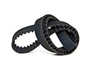 GMC Timing Belt
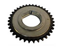 GMC Balance Shaft Gear
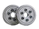 GMC Cam Gear
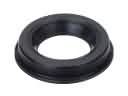 GMC Camshaft Seal
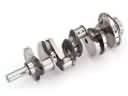 GMC Crankshaft
 GMC Dipstick Tube
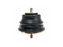 GMC Engine Mount
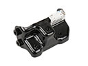 GMC Engine Mount Bracket
 GMC Exhaust Valve
 GMC Oil Drain Plug Gasket
 GMC Oil Pan Gasket
 GMC Pushrod
Browse GMC Camshaft by Models
Acadia Sierra 1500 Yukon Canyon Sierra 2500 HD Terrain Envoy Sonoma Typhoon Caballero C1500 Envoy XL Envoy XUV Jimmy K1500 S15 S15 Jimmy Safari Savana 2500 Savana 3500 Sierra 2500 Sierra 3500 Yukon XL Acadia Limited C2500 C3500 G2500 K2500 K3500 Savana 1500 Yukon XL 1500 C1500 Suburban C2500 Suburban G1500 G3500 K1500 Suburban K2500 Suburban P2500 R1500 R1500 Suburban R2500 R2500 Suburban R3500 Sierra 1500 Classic Sierra 1500 HD Sierra 1500 HD Classic Sierra 2500 HD Classic Sierra 3500 Classic Sierra 3500 HD V1500 V1500 Suburban V2500 V2500 Suburban V3500 Yukon XL 2500