ChevyParts
My Garage
My Account
Cart
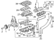
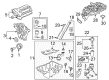
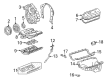
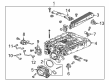
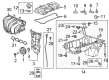
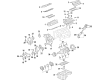
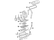
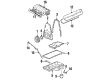
OEM Chevrolet Camaro Intake Manifold
Engine Intake Manifold- Select Vehicle by Model
- Select Vehicle by VIN
Select Vehicle by Model
orMake
Model
Year
Select Vehicle by VIN
For the most accurate results, select vehicle by your VIN (Vehicle Identification Number).
18 Intake Manifolds found


Chevrolet Camaro Intake Manifold Part Number: 12629466
$315.36 MSRP: $541.48You Save: $226.12 (42%)Ships in 1-2 Business Days
Chevrolet Camaro Intake Manifold Part Number: 12642700
$325.89 MSRP: $559.58You Save: $233.69 (42%)
Chevrolet Camaro Intake Manifold Part Number: 10137051
$312.08 MSRP: $417.28You Save: $105.20 (26%)Ships in 1-2 Business Days
Chevrolet Camaro Intake Manifold Part Number: 12713783
$3811.31 MSRP: $6012.60You Save: $2201.29 (37%)
Chevrolet Camaro Intake Manifold Part Number: 12713777
$3565.87 MSRP: $5626.00You Save: $2060.13 (37%)Ships in 1-3 Business Days
Chevrolet Camaro Intake Manifold Part Number: 12674143
$156.80 MSRP: $258.22You Save: $101.42 (40%)Ships in 1-2 Business Days
Chevrolet Camaro Intake Manifold Part Number: 12631023
$269.56 MSRP: $444.06You Save: $174.50 (40%)
Chevrolet Camaro Intake Manifold Part Number: 12611155
$348.50 MSRP: $574.12You Save: $225.62 (40%)Ships in 1-2 Business Days

Chevrolet Camaro Intake Manifold Part Number: 12686561
$594.25 MSRP: $939.22You Save: $344.97 (37%)
Chevrolet Camaro Intake Manifold Part Number: 88894339

Chevrolet Camaro Intake Manifold Part Number: 24505829
Chevrolet Camaro Intake Manifold Part Number: 12561269

Chevrolet Camaro Intake Manifold Part Number: 12552137
Chevrolet Camaro Intake Manifold Part Number: 12518284

Chevrolet Camaro Intake Manifold Part Number: 10118668

Chevrolet Camaro Intake Manifold, Upper Part Number: 24505921
Chevrolet Camaro Intake Manifold Part Number: 24505487

Chevrolet Camaro Intake Manifold Part Number: 12595765
$267.44 MSRP: $420.63You Save: $153.19 (37%)
Chevrolet Camaro Intake Manifold
Want to cut long-term maintenance and repair costs? Choose OEM Intake Manifold. Those parts deliver top durability you can trust. On our site, you'll find a huge catalog of genuine Chevrolet Camaro parts. Prices are unbeatable, so you can keep more in your pocket. Every OEM Chevrolet Camaro Intake Manifold includes a manufacturer's warranty. You can also get an easy return policy that keeps buying risk free. Fast delivery, get your car on the road quickly. It's simple to search, compare, and order. Stop guessing about quality or fit. Order today and save with parts that last.
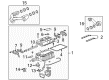
Intake Manifold of Camaro automobiles models is integral to the performance of the engine by supplying air and fuel to the cylinder. Its main purpose is to divide the air-fuel mixture in equal portions to ensure proper combustion of the mixture. Made earlier from aluminum or die cast iron, new generation Chevrolet Camaro intake manifolds can come as plastic like composites for better air flow and lighter in weights. Other designs include variable-length intake manifolds (VLIM) among others that aim at increasing the power and fuel efficiency. These systems modify the volume of the intake pipe as a function of load employing principles such as Venturi technology and Helmholtz frequency resonance to charge the engine in lieu of directly controlling flow. In general, it is clear that the Chevrolet Camaro has made enhancement in the intake manifold technology thus enhancing the performance and efficiency of the car's engine.
Chevrolet Camaro Intake Manifold Parts Questions & Experts Answers
- Q: How to replace the upper intake manifold on Chevrolet Camaro?A:You must start by draining engine coolant and disconnecting both the iat sensor electrical connection and upper Intake Manifold. Start by disconnecting the right side fuel injector electrical connectors from the fuel injectors and the manifold absolute pressure (MAP) sensor electrical connector . Next remove the air intake duct and the drive belt tensioner. Extract the engine harness vacuum tube from its space at the vacuum port while also extracting the fuel pressure regulator tube from the manifold vacuum source and the fuel pressure regulator valve . Remove both left side fuel injector connectors as well as the evaporative emission (EVAP) canister purge valve switch connector. Begin by releasing fuel pressure and removing both fuel lines from the Fuel Rail along with disconnecting the evap canister purge valve fuel vapor line. The first step is to disconnect the Ignition Control Module followed by relocating the brake booster hose clamp before disconnecting the brake booster hose through the upper Intake Manifold fitting. Disconnect the electronic throttle control (ETC) electrical connector and the mass airflow (MAF) sensor and engine coolant temperature (ECT) sensor electrical connectors. You must detach the Throttle Body engine harness clip while also removing the engine harness clamp bolt and harness clamp so you can place the engine wiring harness into position. Pull out the Thermostat Housing and disconnect the wiring harness clips from the Fuel Rail before moving the wiring harness aside. Use compressed air to clean away any dirt from the injector bores before removing the Fuel Rail from the upper Intake Manifold by removing its Fuel Rail nuts. You must first remove upper Intake Manifold bolts (1, 3, 4) before extracting the upper Intake Manifold with its matching upper Intake Manifold gasket . During cleaning operations inspect and tidy up the mating surfaces for upper and lower intake manifolds. Additionally clean away the manifold vacuum source screws and manifold vacuum source , the evap purge valve bolts and purge valve , the Throttle Body bolt , nuts , throttle body , and gasket . The lower Intake Manifold o-ring seals (3, 4) must be removed when needed. Installation of new lower Intake Manifold o-ring seals (3, 4) begins before positioning the upper Intake Manifold gasket and upper Intake Manifold onto the lower Intake Manifold. Tighten the 9 upper Intake Manifold bolts to 15 nm (11 ft. Lbs.), the 2 upper Intake Manifold bolts to 30 nm (22 ft. Lbs.)use 15 nm (11 ft. Lbs.) to tighten the upper Intake Manifold bolt. If the upper Intake Manifold was replaced, install the Throttle Body Gasket and Throttle Body , followed by the Throttle Body bolt and nuts , tightening the Throttle Body nuts to 10 nm (89 inch lbs.) secure the Throttle Body bolt by applying 10 nm torque (89 inch lbs.). Fasten the Fuel Rail to the upper Intake Manifold by tightening Fuel Rail nuts to a torque of 9 nm (80 inch lbs.). Fasten the wiring harness clips to both the Fuel Rail and the Thermostat Housing before repositioning the engine harness. Install the engine harness clamp and harness clamp bolt , tightening the harness clamp bolt to 6 nm (53 inch lbs.)install the engine harness clip to the Throttle Body after securing the engine harness clamp with the harness clamp bolt at 6 nm (53 inch lbs.). First connect the maf sensor's electrical connector then the ect sensor's electrical connector before connecting the etc electrical connector . Place the brake booster hose onto the upper Intake Manifold fitting then secure the brake booster hose clamp at its position. Set the Ignition Control Module in place and install the evap canister purge valve to the upper Intake Manifold using 10 nm (89 inch lbs.) torque. The fuel vapor line should be connected to the evap canister purge valve and the fuel lines should lead to the Fuel Rail. Install the evap canister purge valve electrical connector and left side fuel injector electrical connectors to their proper positions on the fuel injectors. The installation of the upper Intake Manifold requires you to secure the manifold vacuum source using 10 nm (89 inch lbs.) torque. Route the fuel pressure regulator tube to connect both the manifold vacuum source and fuel pressure regulator valve and route the engine harness vacuum tube to join the vacuum port and fit the MAP Sensor electrical connector and right side fuel injector electrical connectors to their respective fuel injectors. Spread out by reconnecting the iat sensor electrical connector followed by adding fresh engine coolant to the system. Last, position the drive belt tensioner and install the air intake duct.

Related Chevrolet Camaro Parts
 Chevrolet Camaro Air Filter
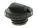 Chevrolet Camaro Gas Cap
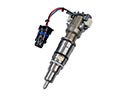 Chevrolet Camaro Fuel Injector
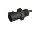 Chevrolet Camaro Air Charge Temperature Sensor
 Chevrolet Camaro Fuel Line Clamps
 Chevrolet Camaro Fuel Pump Gasket
 Chevrolet Camaro Fuel Pump Seal
 Chevrolet Camaro Fuel Tank
 Chevrolet Camaro Fuel Tank Filler Neck
 Chevrolet Camaro PCV Valve Elbow
 Chevrolet Camaro Throttle Body
 Chevrolet Camaro Throttle Body Gasket