ChevyParts
My Garage
My Account
Cart
OEM GMC Engine Control Module
Engine Control Computer- Select Vehicle by Model
- Select Vehicle by VIN
Select Vehicle by Model
orMake
Model
Year
Select Vehicle by VIN
For the most accurate results, select vehicle by your VIN (Vehicle Identification Number).
108 Engine Control Modules found


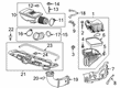
 Product Specifications
- Other Name: Module, Emission Control System; Engine Control Module


 Product Specifications
- Other Name: Module Assembly-Engine Control (W/2ND Mpu) E92 Service ECM 2-Byte; Engine Control Module
- Replaced by: 12704477

 Product Specifications
- Other Name: Module Assembly-Engine Control (W/2ND Mpu) E92 Service ECM, 5 Byt; Engine Control Module
- Replaced by: 12704476

 Product Specifications
- Other Name: Module Assembly-Engine Control (W/2ND Mpu); Engine Control Module

 Product Specifications
- Other Name: Module Assembly-Engine Control (W/O Calibration); Module, Emission Control System
- Replaces: 24001263, 24000211, 24001862

 Product Specifications
- Other Name: Module Assembly-Engine Control (W/2ND Mpu); Module, Emission Control System
- Replaces: 12711509, 12683624, 12670950, 12686363, 12700911

 Product Specifications
- Other Name: Module, Emission Control System; Engine Control Module; ECM

 Product Specifications
- Other Name: Module Assembly-Engine Control (W/2ND Mpu); Module, Emission Control System
- Replaces: 55501366, 24000466

 Product Specifications
- Other Name: Module Assembly-Engine Control (W/O Calibration); Module, Emission Control System
 Product Specifications
- Other Name: Module Assembly-Engine Control (W/ 2ND Mpu) & (W/O C; Module, Emission Control System
- Replaces: 55512265
- Product Specifications
- Other Name: Module Assembly-Engine Control (W/2ND Mpu); Module, Emission Control System
- Replaces: 24000462, 55487860, 55591599

 Product Specifications
- Other Name: Module Assembly-Engine Control (W/2ND Mpu) E78 Service No Start; Engine Control Module; Module, Emission Control System
- Replaces: 12616532, 12670036, 12642100
 Product Specifications
- Other Name: Module Assembly, Engine Control (W/2ND Mpu); Engine Control Module; Module, Emission Control System

 Product Specifications
- Other Name: Module, Emission Control System; Engine Control Module; ECM
- Replaced by: 19433896

 Product Specifications
- Other Name: Module Assembly-Engine Control (W/O Calibration); Module, Emission Control System
- Replaces: 12718010
 Product Specifications
- Other Name: Module Assembly-Engine Control (W/O Calibration); Module, Emission Control System
- Replaces: 12711353

 Product Specifications
- Other Name: Module, Powertrain Control (P59)
- Replaced by: 89017749
GMC Control Module Part Number: 16215830
$139.06 MSRP: $261.14You Save: $122.08 (47%)Ships in 1-2 Business DaysProduct Specifications- Other Name: Module, Emission Control System; Engine Control Module; EEC Module; Radio; PCM; ECM

 Product Specifications
- Other Name: Module Assembly-Engine Control (W/O Calibration); Module, Emission Control System
- Replaces: 24001956
- Product Specifications
- Other Name: Module Assembly-Engine Control (W/2ND Mpu); Module, Emission Control System
- Replaces: 24000461, 55502052
| Page 1 of 6 |Next >
1-20 of 108 Results
GMC Engine Control Module
Want to cut long-term maintenance and repair costs? Choose OEM Engine Control Module. Those parts deliver top durability you can trust. On our site, you'll find a huge catalog of genuine GMC parts. Prices are unbeatable, so you can keep more in your pocket. Every OEM GMC Engine Control Module includes a manufacturer's warranty. You can also get an easy return policy that keeps buying risk free. Fast delivery, get your car on the road quickly. It's simple to search, compare, and order. Stop guessing about quality or fit. Order today and save with parts that last.
GMC Engine Control Module Parts Questions & Experts Answers
- Q: What does the service of the engine control module (ECM) typically involve on GMC Canyon?A:The service of a powertrain control module (PCM) includes two main approaches: either PCM replacement or EEPROM electrically erasable programmable read-only memory programming. The PCM requires an inspection to confirm the correct replacement component will be installed. The next step is to remove the failing PCM before you install the newly obtained service PCM. First scan the tool to obtain engine oil life percentage for programming the new replacement module because inadequate data entry will cause default settings to set oil change intervals at 5000 km (3,000 mi). The disconnect process for PCM harness connectors should happen with ignition OFF to avoid harming internal components. Before connector installation examine the PCM connector surfaces while checking that each gasket is properly installed to avoid contaminant entry. You should disconnect the PCM bracket mounting tabs during PCM removal but keep away from connector pins or soldered components to stop possible electrostatic discharge (ESD) harm. To install the unit place the PCM inside its bracket while making sure the tabs properly interlock before connecting the PCM harness connectors to the body of the PCM. Programming of new PCM units is mandatory after new PCM installation.
- Q: How to replace the Engine Control Module (ECM) on GMC Acadia?A:The procedure for ecm replacement begins with turning off the ignition and using a scan tool to obtain and save the engine oil life and automatic transmission fluid life. Begin by removing the negative Battery Cable before disconnecting middle and lower electrical connectors from the ecm that are fused to the engine wiring harness. The procedure for replacing the ecm bracket requires users to first detach the engine wiring harness clip from its tab on the ecm bracket followed by unconnecting the upper electrical connector from the ecm. The pins on these connectors must not undergo human contact because electrostatic discharges will lead to damage. Use your fingers to raise the retaining tab before sliding out the ecm from its support brackets. Remove ecm bracket bolts only when needed and also detach the bracket. When installing the bracket you may need to position its slots first. Then add the bolts to fasten them at 6 n.m (53 lb in). Place the ecm onto its temporary support tabs after which it can be inserted under the retaining tab. Fit the engine wiring harness upper electrical connector to the ecm followed by installation of the engine wiring harness clip onto the ecm bracket tab when replacement of the ecm bracket occurred. The engine wiring harness middle electrical connector and lower electrical connector must be connected to the ecm before reinstalling the negative Battery Cable. A newly installed ecm requires programming to guarantee proper setup.
- Q: What does the service of the Engine Control Module (ECM) involve on GMC Sierra 1500?A:The service procedure for the pcm control involves replacing the component or executing eeprom operations. When it becomes necessary to replace the pcm always select the appropriate part before uninstalling the faulty module to install a new service pcm. Internal pcm damage will happen when turning off the ignition switch before connecting or disconnecting power to the pcm and clear all debris from the pcm connector surfaces. Maintaining proper connection of pcm module connector gaskets will help stop contaminants from entering the system. Use a scan tool to obtain the engine oil life percentage before removal because a failure to program the new module with this data through default mode will activate a 100% oil life condition which triggers a required oil change at 5000 km (3,000 mi) from the last change. Before work begins disconnect the negative Battery Cable except when using rpo nys which requires removal of the harness ground clip while rpo hp2 demands the removal of the hybrid control module (HCM). Vehicles without rpo hp2 need to start with unhooking the pcm cover mounting tabs before separating the cover from its bracket while removing the cover. Users should perform the identical cover removal steps for vehicles that have rpo hp2 specification. The process starts by removing the pcm electrical connector bolts when the ignition is off to avoid damage followed by disconnecting pcm electrical connectors and releasing the spring latch before extracting the pcm through the mounting tabs. Safely mount the new pcm through its tabs before locking the spring mechanism while connecting electrical cables by tightening the bolts to 8 n.m (71 lb in). Install the pcm cover after which installing the hcm if the vehicle includes rpo hp2. The negative Battery Cable needs to be reconnected after which pcm programming should be performed in case of new unit installation.


Related GMC Parts
 GMC Knock Sensor
 GMC Fuse
 GMC Camshaft Position Sensor
 GMC Ignition Coil
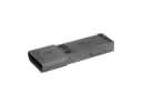 GMC Ignition Control Module
 GMC Ignition Switch
 GMC ABS Relay
 GMC Air Charge Temperature Sensor
 GMC Antenna Cable
 GMC EGR Cooler
 GMC Exhaust Gas Temperature Sensor
 GMC Turn Signal Flasher
Browse GMC Engine Control Module by Models
Acadia Sierra 1500 Yukon Canyon Sierra 2500 HD Terrain Envoy Sonoma Typhoon Syclone Caballero C1500 Envoy XL Envoy XUV Jimmy K1500 S15 S15 Jimmy Safari Savana 2500 Savana 3500 Sierra 2500 Sierra 3500 Yukon XL Acadia Limited C2500 C3500 G2500 K2500 K3500 P3500 Savana 1500 Yukon XL 1500 C1500 Suburban C2500 Suburban G1500 G3500 K1500 Suburban K2500 Suburban P2500 R1500 R1500 Suburban R2500 R2500 Suburban R3500 Sierra 1500 Classic Sierra 1500 HD Sierra 1500 Limited Sierra 2500 HD Classic Sierra 3500 Classic Sierra 3500 HD V1500 V1500 Suburban V2500 V2500 Suburban V3500 Yukon XL 2500