ChevyParts
My Garage
My Account
Cart
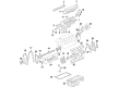
OEM GMC Savana 1500 Harmonic Balancer
Engine Harmonic Balancer- Select Vehicle by Model
- Select Vehicle by VIN
Select Vehicle by Model
orMake
Model
Year
Select Vehicle by VIN
For the most accurate results, select vehicle by your VIN (Vehicle Identification Number).
6 Harmonic Balancers found


GMC Savana 1500 Vibration Damper Part Number: 19300488
$115.88 MSRP: $199.00You Save: $83.12 (42%)Ships in 1-2 Business Days


GMC Savana 1500 Vibration Damper Part Number: 10243271
$91.05 MSRP: $156.37You Save: $65.32 (42%)Ships in 1-2 Business Days


GMC Savana 1500 Vibration Damper Part Number: 10224885
$65.09 MSRP: $106.52You Save: $41.43 (39%)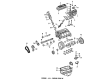
GMC Savana 1500 Vibration Damper Part Number: 19417972
$409.58 MSRP: $650.30You Save: $240.72 (38%)Ships in 1-2 Business DaysGMC Savana 1500 Vibration Damper Part Number: 10243272
$207.93 MSRP: $357.10You Save: $149.17 (42%)Ships in 1-2 Business Days


GMC Savana 1500 Vibration Damper Part Number: 12634105
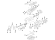
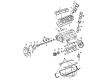
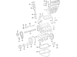
GMC Savana 1500 Harmonic Balancer
Want to cut long-term maintenance and repair costs? Choose OEM Harmonic Balancer. Those parts deliver top durability you can trust. On our site, you'll find a huge catalog of genuine GMC Savana 1500 parts. Prices are unbeatable, so you can keep more in your pocket. Every OEM GMC Savana 1500 Harmonic Balancer includes a manufacturer's warranty. You can also get an easy return policy that keeps buying risk free. Fast delivery, get your car on the road quickly. It's simple to search, compare, and order. Stop guessing about quality or fit. Order today and save with parts that last.
GMC Savana 1500 Harmonic Balancer Parts Questions & Experts Answers
- Q: How to replace the harmonic balancer on GMC Savana 1500?A:A replacement procedure for crankshaft balancer starts by disconnecting the Battery Cable's negative end then continuing with removing both the Fan Shroud assembly and Drive Belt. After removing the crankshaft balancer bolt with its washer you must detach the bolts which hold the Crankshaft Pulley in place. Use the balancer remover and installer (J 23523-F) to uninstall a crankshaft balancer by mounting the j 23523-f plate with bolts onto the component before torquing bolts to 25 nm (18 ft. Lbs.), then placing the j 23523-f forcing screw into this plate. To extract the balancer the j 23523-f forcing screw should be rotated clockwise before tool removal. Check the position and length of front groove pins when present before thoroughly cleaning all parts for inspection. The front seal of the crankshaft front cover requires application of grease during reinstallation when using the existing seal while maintaining proper position of the front groove pin. Place gm p/n 12346141 adhesive or an equivalent substance onto the crankshaft balancer keyway then position this mark with the balancer key before you fasten the balancer to the crankshaft. Start by placing the j 23523-f onto the crankshaft using its plate and bolts which need to be tightened to 25 nm (18 ft. Lbs.). Proceed to add the j 23523-f screw then the bearing and washer followed by the nut until the balancer hub rests against the crankshaft position sensor reluctor ring during a clockwise rotation. The j 23523-f should be removed while you install the Crankshaft Pulley and bolts with 58 nm (43 ft. Lbs.) torque value. Then align the crankshaft balancer washer crown to face outward from the engine before installing the washer and bolt which must be tightened to 95 nm (70 ft. Lbs.). Reinstall the Drive Belt before adding the Fan Shroud assembly and then reattach the battery negative cable.

Related GMC Savana 1500 Parts
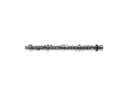 GMC Savana 1500 Camshaft
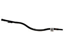 GMC Savana 1500 Dipstick Tube
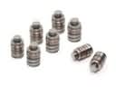 GMC Savana 1500 Lash Adjuster
 GMC Savana 1500 Motor And Transmission Mount
 GMC Savana 1500 Oil Pan Gasket
 GMC Savana 1500 Oil Pump
 GMC Savana 1500 Piston
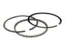 GMC Savana 1500 Piston Ring
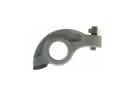 GMC Savana 1500 Rocker Arm
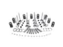 GMC Savana 1500 Rocker Shaft Spring Kit
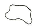 GMC Savana 1500 Timing Chain
 GMC Savana 1500 Valve Cover Grommet