ChevyParts
My Garage
My Account
Cart
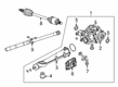
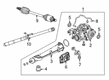
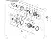
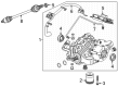
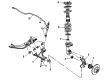
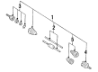
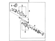
OEM Buick Axle Shaft
Car Axle Shaft- Select Vehicle by Model
- Select Vehicle by VIN
Select Vehicle by Model
orMake
Model
Year
Select Vehicle by VIN
For the most accurate results, select vehicle by your VIN (Vehicle Identification Number).
261 Axle Shafts found

Buick Axle Assembly, Driver Side Part Number: 84173833
$233.86 MSRP: $367.99You Save: $134.13 (37%)Ships in 1-3 Business DaysProduct Specifications- Other Name: Shaft Assembly, Rear Wheel Drive; Axle Shaft; Shaft, Rear Axle Drive
- Position: Driver Side
- Replaces: 23285497, 84173830, 22995300

Buick Axle Assembly, Rear Driver Side Part Number: 84173839
$138.40 MSRP: $217.76You Save: $79.36 (37%)Ships in 1-3 Business DaysProduct Specifications- Other Name: Shaft Assembly-Rear Wheel Drive; Axle Shaft; Shaft, Rear Axle Drive
- Position: Rear Driver Side

Buick Axle Assembly, Front Driver Side Part Number: 84698781
$201.85 MSRP: $317.60You Save: $115.75 (37%)Ships in 1-3 Business DaysProduct Specifications- Other Name: Shaft Assembly-Front Wheel Drive Half; Axle Shaft; Shaft, Front Wheel Drive Axle
- Position: Front Driver Side
- Replaced by: 85558611

Buick Axle Assembly, Rear Driver Side Part Number: 84265826
$149.61 MSRP: $235.40You Save: $85.79 (37%)Ships in 1-2 Business DaysProduct Specifications- Other Name: Shaft Assembly-Rear Wheel Drive; Axle Shaft; Shaft, Rear Axle Drive
- Position: Rear Driver Side
- Replaced by: 86585861
Buick Axle Assembly, Front Passenger Side Part Number: 84559703
$203.60 MSRP: $320.35You Save: $116.75 (37%)Ships in 1-3 Business DaysProduct Specifications- Other Name: Shaft Assembly-Front Wheel Drive Half; Axle Shaft; Shaft, Front Wheel Drive Axle
- Position: Front Passenger Side
- Replaced by: 85558608

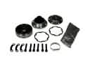
Buick Axle Shaft, Front Passenger Side Part Number: 26018518
$469.19 MSRP: $741.57You Save: $272.38 (37%)Ships in 1-3 Business DaysProduct Specifications- Other Name: Shaft Kit-Front Wheel Drive; CV Axle Assembly; CV Axle; Drive Axle; Axle Assembly; Shaft Kit, Front Wheel Drive Axle
- Position: Front Passenger Side

Buick Axle Assembly, Front Part Number: 26008315
$33.71 MSRP: $716.13You Save: $682.42 (96%)Ships in 1-2 Business DaysProduct Specifications- Other Name: Shaft Kit, Front Wheel Drive Axle; CV Axle Assembly; Axle Shaft; CV Axle
- Position: Front
Buick Axle Assembly, Rear Driver Side Part Number: 84173841
$113.07 MSRP: $177.91You Save: $64.84 (37%)Product Specifications- Other Name: Shaft Assembly-Rear Wheel Drive; Axle Shaft; Shaft, Rear Axle Drive
- Position: Rear Driver Side

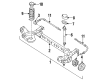
Buick Axle Beam, Rear Part Number: 18023242
Product Specifications- Other Name: Axle, Rear; Axle, Rear Axle
- Position: Rear

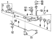
Buick Axle Assembly, Rear Part Number: 22610948
Product Specifications- Other Name: Axle, Rear; Axle Shaft; Axle, Rear Axle
- Position: Rear

Buick Axle Shaft, Front Driver Side Part Number: 26023083
Product Specifications- Other Name: Shaft, Front Wheel Drive; Shaft, Front Wheel Drive Axle
- Position: Front Driver Side
Buick Axle Assembly, Front Driver Side Part Number: 26059859
Product Specifications- Other Name: Shaft Kit, Front Wheel Drive; CV Axle Assembly; Axle Shaft; CV Axle; Shaft Kit, Front Wheel Drive Axle
- Position: Front Driver Side
- Replaces: 26034302
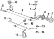
Buick Axle Assembly, Rear Part Number: 18023241
Product Specifications- Other Name: Axle, Rear Axle; Axle Shaft; Axle Beam
- Position: Rear

Buick Axle Shaft, Front Driver Side Part Number: 26018519
Product Specifications- Other Name: Shaft Kit-Front Wheel Drive; CV Axle Assembly; CV Axle; Axle Assembly; Shaft Kit, Front Wheel Drive Axle
- Position: Front Driver Side

Buick Axle Assembly, Front Driver Side Part Number: 26034305
Product Specifications- Other Name: Shaft Kit, Front Wheel Drive; Axle Shaft; Shaft Kit, Front Wheel Drive Axle
- Position: Front Driver Side

Buick Axle Assembly, Front Part Number: 26018521
Product Specifications- Other Name: Shaft Kit-Front Wheel Drive; CV Axle Assembly; Axle Shaft; CV Axle; Shaft Kit, Front Wheel Drive Axle
- Position: Front
Buick Axle Assembly, Front Part Number: 26018520
Product Specifications- Other Name: Shaft Kit-Front Wheel Drive; CV Axle Assembly; Axle Shaft; CV Axle; Shaft Kit, Front Wheel Drive Axle
- Position: Front
Buick Axle Assembly, Front Passenger Side Part Number: 26018511
Product Specifications- Other Name: Shaft Kit-Front Wheel Drive; Axle Shaft; Shaft Kit, Front Wheel Drive Axle
- Position: Front Passenger Side
Buick Axle Assembly, Front Passenger Side Part Number: 26059858
Product Specifications- Other Name: Shaft Kit, Front Wheel Drive; CV Axle Assembly; Axle Shaft; CV Axle; Shaft Kit, Front Wheel Drive Axle
- Position: Front Passenger Side
- Replaces: 26034303
Buick Axle Beam, Rear Part Number: 18023306
Product Specifications- Other Name: Axle, Rear Axle
- Position: Rear
| Page 1 of 14 |Next >
1-20 of 261 Results
Buick Axle Shaft
Want to cut long-term maintenance and repair costs? Choose OEM Axle Shaft. Those parts deliver top durability you can trust. On our site, you'll find a huge catalog of genuine Buick parts. Prices are unbeatable, so you can keep more in your pocket. Every OEM Buick Axle Shaft includes a manufacturer's warranty. You can also get an easy return policy that keeps buying risk free. Fast delivery, get your car on the road quickly. It's simple to search, compare, and order. Stop guessing about quality or fit. Order today and save with parts that last.
Buick Axle Shaft Parts Questions & Experts Answers
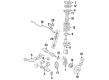
- Q: How to replace the front axle shaft on Buick Park Avenue?A:Vehicle front Axle Shaft replacement requires vehicle support followed by tire and wheel assembly removal. Uncouple the outer Tie Rod End from the Steering Knuckle but keep the Tie Rod End jam nut intact. Use a drift or punch tool to insert inside the brake rotor but press against the brake caliper to stop Wheel Hub and bearing movement. Anytime a Spindle Nut removal occurs you must install a fresh new nut before discarding the previous Spindle Nut. Disconnect the electrical connector from the sensor before moving the wheel speed sensor wiring harness to a location that's away from the Ball Joint. First disable the wheel speed sensor electrical connector then reposition the wiring harness before disconnecting the Ball Joint from the Steering Knuckle. Use the Wheel Hub remover (J42129) to detach the hub assembly by tightening wheel nuts while you support the Axle Shaft until complete removal. Through the use of Wheel Hub remover (J42129) operators can separate the Axle Shaft from the Wheel Hub and bearing by providing support during the operation. Disassemble the slide hammer with adapter (J2619-01) and extension (J29794) and Axle Shaft puller (J33008-A) to use them for Axle Shaft separation from transaxle and vehicle removal. To install the Axle Shaft place it into the transaxle then evaluate its correct seating by grasping the inner tripot housing for outward movement. Mount the Axle Shaft onto the hub and bearing while hooking up the Ball Joint to the Steering Knuckle also reattach the wheel speed sensor electrical connector. A drift or punch should be inserted through the rotor to prevent hub and bearing rotation during installation of the stabilizer shaft link. Place a new Axle Shaft Spindle Nut into position then torque it to 160 nm (118 ft. Lbs.). After connecting the outer Tie Rod End to the Steering Knuckle you should install the tire and wheel assembly followed by lowering the vehicle.
- Q: How to replace the rear axle shaft on Buick Rainier?A:The first step toward rear Axle Shaft replacement starts by lifting the vehicle and removing its wheel and tire. Proceed with breaking caliper removal as well. Start by removing the rear axle housing cover together with its gasket before disconnecting the pinion shaft locking bolt. Rear axle shafts without Differential locking must have their pinion shafts removed. You should partially remove the shaft of vehicles with locking differentials to rotate the case until the pinion shaft makes contact with the housing. To extract the Axle Shaft use a screwdriver for c-lock rotation until it reaches the thrust block position. Then push the Axle Shaft flange toward the Differential while removing the c-lock from the Axle Shaft opening to proceed with shaft removal by avoiding any shaft rotation to prevent gear misalignment. When installing the Axle Shaft into the rear axle housing ensure that the Differential side gear receives the splines without damaging the seal. You must apply the c-lock to the button end of an Axle Shaft that lacks a locking Differential function. When operating a locking Differential users need to keep the pinion shaft partially protruding and apply the c-lock to the Axle Shaft until both ends meet the thrust block. Sitting the c-lock inside the Differential gear requires flange shaft extension until positioning the pinion shaft hole with the Differential case bolt hole. After installing a new pinion shaft locking bolt, tighten it to 36 nm (27 ft. Lbs.). The last steps include installing the rear axle housing cover with gasket and brake caliper and tire and wheel assembly while filling it with planned axle lubricant before lowering the vehicle.
- Q: How to replace the rear wheel axle shaft on Buick Rendezvous?A:The process of replacing a rear wheel drive shaft begins by activating the parking brake and then elevating and supporting the motor vehicle. The tire assembly needs replacement while discarding the wheel drive shaft nut as you must use a new shaft nut. First deactivate the parking brake and then take off the Brake Caliper Bracket. Proceed to remove the nut holding the park brake cable routing bracket and the bolt that retains the rear Tie Rod End from the rear suspension knuckle yet keep the Tie Rod End jam nut tight. Separate the suspension knuckle bolts which fasten the park brake cable bracket and cut the wheel speed sensor electrical connector free. Mount the Wheel Hub remover (J 42129) to the Wheel Hub while fastening it with wheel nuts before starting to disconnect the wheel drive shaft yet retaining the Wheel Hub and bearing. Start by dismantling the upper Control Arm bolt and nut which attaches to the suspension knuckle before proceeding with total wheel drive shaft disintegration. Place the suspension knuckle behind the vehicle while you remove the Wheel Hub remover (J 42129). First support the wheel drive shaft before completing its removal. Then install together Axle Shaft puller (J 33008-A), Axle Shaft remover extension (J 29794), and slide hammer (J 2619-O1). It is necessary to install the Axle Shaft puller (J 33008-A) onto the rear beveled surface of the wheel drive shaft inner joint housing followed by using the assembled tools to disengage the wheel drive shaft from the rear axle Differential before wheel drive shaft removal from the vehicle. When changing the rear wheel drive shaft it becomes necessary to replace the Differential output shaft oil seal because this part cannot be reused during this process. Support the wheel drive shaft until installation completion before you guide it onto the Differential output shaft while using light force for installation. The wheel drive shaft requires full seating position on the Differential output shaft retaining ring. After positioning the suspension knuckle near the wheel drive shaft establish proper alignment to the hub and bearing but keep it from reaching full seating before aligning it with the upper Control Arm. Tighten the bolt between upper Control Arm/suspension knuckle assembly which reaches 85 nm (63 ft. Lbs. Torque). After establishing the park brake cable bracket in its position the technician should attach the rear Tie Rod to the rear suspension knuckle before tightening the Tie Rod-to-knuckle bolt to 85 nm (63 ft. Lbs.). Install the Brake Caliper Bracket first before connecting the wheel speed sensor electrical connector and installing the park brake cable routing bracket and its nut and tightening it to 10 nm (89 inch lbs.). Set the park brake and install the new wheel drive shaft Spindle Nut slowly until it draws the wheel drive shaft spindle inside the Wheel Hub and bearing then fully tighten to 260 nm (192 ft. Lbs.). The tire and wheel assembly should be reinstalled then the vehicle needs to be lowered before releasing the park brake.


Related Buick Parts
 Buick CV Joint
 Buick Alignment Bolt
 Buick Ball Joint
 Buick Front Cross-Member
 Buick Lateral Link
 Buick Ride Height Sensor
 Buick Shock Absorber
 Buick Shock And Strut Mount
 Buick Shock and Strut Boot
 Buick Steering Knuckle
 Buick Trailing Arm
 Buick Wheel Cover