ChevyParts
My Garage
My Account
Cart
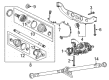
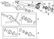
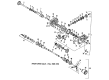
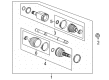
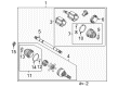
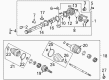
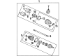
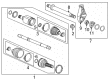
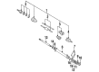
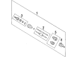
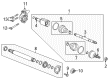
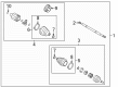
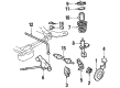
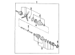
OEM Buick CV Joint
CV Joint Axle- Select Vehicle by Model
- Select Vehicle by VIN
Select Vehicle by Model
orMake
Model
Year
Select Vehicle by VIN
For the most accurate results, select vehicle by your VIN (Vehicle Identification Number).
104 CV Joints found


Buick Outer CV Joint Part Number: 95908454
$137.99 MSRP: $217.13You Save: $79.14 (37%)Ships in 1-3 Business DaysProduct Specifications- Other Name: Joint Kit, Front Wheel Drive Axle; CV Joint; Outer Joint; Joint Kit, Rear Axle Universal Joint
- Position: Front Outer


Buick Inner Joint, Front Part Number: 13318019
$102.81 MSRP: $180.37You Save: $77.56 (43%)Ships in 1-2 Business DaysProduct Specifications- Other Name: Joint Kit, Front Wheel Drive Axle; CV Joint
- Position: Front

Buick CV Joints Part Number: 7846866
$95.91 MSRP: $171.26You Save: $75.35 (44%)Ships in 1-3 Business DaysProduct Specifications- Other Name: Spider Kit - Tripot; CV Joint; Spider Kit
- Replaced by: 26005377
Buick CV Joints Part Number: 26005377
$95.91 MSRP: $171.26You Save: $75.35 (44%)Ships in 1-3 Business DaysProduct Specifications- Other Name: CV Joint; Spider Assembly; Joint Assembly; Inner Joint; Inner Joint Assembly
- Replaces: 07846866, 7846866

Buick Inner CV Joint, Front Part Number: 26059677
$46.64 MSRP: $564.50You Save: $517.86 (92%)Ships in 1-2 Business DaysProduct Specifications- Other Name: Joint Kit, Front Wheel Drive Axle; Joint Assembly; Inner Joint; Inner Joint Assembly
- Position: Front

Buick Inner Joint, Front Driver Side Part Number: 84517820
$173.04 MSRP: $272.27You Save: $99.23 (37%)Ships in 1-3 Business DaysProduct Specifications- Other Name: Joint Kit, Front Wheel Drive Axle; CV Joint
- Position: Front Driver Side

Buick Outer Joint, Inner Part Number: 84282538
$98.73 MSRP: $154.62You Save: $55.89 (37%)Ships in 1-3 Business DaysProduct Specifications- Other Name: Inner CV Joint; CV Joint
- Position: Inner
- Replaces: 84282511
Buick Inner Joint, Front Passenger Side Part Number: 84517821
$102.89 MSRP: $161.14You Save: $58.25 (37%)Ships in 1-3 Business DaysProduct Specifications- Other Name: Joint Kit, Front Wheel Drive Axle; CV Joint
- Position: Front Passenger Side

Buick Outer CV Joint, Front Part Number: 88897261
$269.38 MSRP: $423.85You Save: $154.47 (37%)Ships in 1-3 Business DaysProduct Specifications- Other Name: Joint Kit, Front Wheel Drive Shaft CV; CV Joint; Outer Joint
- Position: Front

Buick Inner Joint, Rear Part Number: 22783790
$156.51 MSRP: $248.49You Save: $91.98 (38%)Ships in 1-2 Business DaysProduct Specifications- Other Name: Housing-Rear Wheel Drive Shaft Tri-Pot Joint
- Position: Rear

Buick CV Joints, Front Part Number: 26075588
$269.62 MSRP: $609.63You Save: $340.01 (56%)Ships in 1-2 Business DaysProduct Specifications- Other Name: Joint Kit, Front Wheel Drive Axle; CV Joint; Inner CV Joint; Inner Joint; Inner Joint Assembly
- Position: Front

Buick Outer CV Joint Part Number: 95908458
$160.73 MSRP: $252.89You Save: $92.16 (37%)Ships in 1-3 Business DaysProduct Specifications- Other Name: Joint Kit, Front Wheel Drive Axle; CV Joint; Outer Joint
- Position: Front Outer

Buick C.V. Joint Part Number: 26020959
Product Specifications- Other Name: CV Joints; Outer Joint; Outer Joint Assembly; Joint Kit, Front Wheel Drive Axle; CV Joint
Buick C.V. Joint Part Number: 26020958
Product Specifications- Other Name: CV Joints; Outer Joint; Joint Kit, Front Wheel Drive Axle; CV Joint
Buick Outer Joint, Inner Part Number: 84282539
$73.61 MSRP: $115.30You Save: $41.69 (37%)Product Specifications- Other Name: Inner CV Joint; CV Joint
- Position: Inner
- Replaces: 38028718

Buick CV Joints, Inner Part Number: 39196365
$104.07 MSRP: $163.02You Save: $58.95 (37%)Product Specifications- Other Name: Inner CV Joint; Outer CV Joint; Outer Joint; Joint Kit, Front Wheel Drive Axle
- Position: Inner
- Replaces: 13333929

Buick Inner CV Joint, Front Part Number: 13296195
$117.61 MSRP: $185.07You Save: $67.46 (37%)Product Specifications- Other Name: Joint Kit, Front Wheel Drive Axle; Inner Joint
- Position: Front

Buick Outer CV Joint Part Number: 25766430
Product Specifications- Other Name: Joint; CV Joint; Outer Joint Assembly

Buick C.V. Joint, Front Part Number: 26020962
Product Specifications- Other Name: Joint Kit; Axle Shaft; CV Joint; CV Boot; CV Joints, Axle Boots, Shaft Assembly, Joint Kit for Front Wheel Drive Axle.
- Position: Front
Buick CV Joints, Driver Side Part Number: 26023218
Product Specifications- Other Name: Joint Kit; CV Joint; Inner Joint Assembly; Joint Kit, Front Wheel Drive Axle
- Position: Driver Side
| Page 1 of 6 |Next >
1-20 of 104 Results
Buick CV Joint Parts Questions & Experts Answers
- Q: How to Properly Service and Replace a CV Boot and CV Joint on a Front Wheel Drive Shaft for a Buick Enclave?A: Before beginning front wheel drive shaft outer joint and boot replacement start by removing the drive shaft from the vehicle then position the drive Axle Shaft inside a soft jawed vice but avoid cutting through either boot because this will damage the sealing surface leading to premature wear. A flat-bladed tool removes the boot clamp from both the cv joint and boot before moving to use side cutters on the boot clamp of the wheel drive shaft and boot. Replace old boot clamps with brand new ones. To continue, use a block of wood with a hammer to detach the cv joint from the wheel drive shaft followed by removing the boot from the wheel drive shaft. Check for signs of damage as well as wearative indicators on your outer cv joint. The boot needs to be aligned onto the wheel drive shaft so it fits correctly within its grooved surface. Put about half the lubricant from the service kit inside the outboard boot before filling the cv joint with remaining lubricant. Begin installation by putting the cv joint on the wheel drive shaft then apply a block of wood and a hammer for mounting. Afterward attach the boot clamp to the wheel drive shaft and boot before moving onto the boot clamp on the boot and cv joint housing . The boot clamp must extend seamlessly across the entire boot circumference while staying within a measurement range of 1.9 mm (0.07 in). Use j 35910 - drive axle seal clamp pliers to secure the boot clamp until the gap reaches 1.9 mm (0.07 in). When working on vehicles with earless type clamps use ch 48894 - wheel drive shaft boot clamp pliers to safely close the boot clamp properly. Move the wheel drive shaft circularly at least four to five times to distribute the lubricant within the outer cv joint then remove the assembly from the bench vise to proceed.
- Q: How to replace the front wheel drive shaft inner CV joint and seal on Buick Regal?A: Other tools required for wheel drive shaft inner joint and seal replacement include you will need swage tool (J 41048) and snap ring pliers (J 8059) and seal clamp tool (J 35910). Swage tool (J 41048), snap ring pliers (J 8059), and seal clamp tool (J 35910). Start your procedure with swage ring removal from the halfshaft bar using a hand grinder which should preserve the halfshaft bar integrity. Separate the inboard seal from the trilobal tripot bushing at the large diameter by pulling it away from the joint along the halfshaft bar. Next, use side cutters to remove and discard the large seal retaining clamp from the tripot joint. Through the use of snap ring pliers (J 8059) separate the spacer ring across its tapered surface. Put the spacer ring along with the tripot joint spider onto the halfshaft bar before removing its retaining ring from the groove to extract this assembly from the halfshaft bar. Use cleaning solvent to completely clean both the tripot joint spider assembly and housing before drying all components thoroughly. During the cleaning process remove all old grease and contaminants. Check both the inboard seal and tripot joint spider assembly as well as the housing and trilobal tripot bushing for any damage or signs of wear. First put the new swage ring onto the inboard seal neck without the swaging process before placing the halfshaft inboard seal onto the halfshaft bar's grooved section. Apply the swage tool (J 41048) to set correctly the inboard portion of the halfshaft assembly with special attention to avoiding damage at the inboard seal. Swage rings should be aligned then tightened using the tool while inspecting the rings for deformities before possible re-swaging. Slip the spacer ring onto the halfshaft bar with the tripot spider's counterbored face facing the halfshaft bar end before inserting the tripot joint spider assembly toward the spacer ring. Position the halfshaft bar retaining ring using snap ring pliers (J 8059) while installing it into its groove and repositioning the spacer ring before applying the service kit grease to both the inboard seal and housing. Insert the trilobal tripot bushing into the housing while making sure it rests flush before placing the bigger new clamp onto the inboard seal for sliding the housing toward the tripot joint spider assembly. Position the joint assembly at the correct vehicle dimension with the inboard seal and housing and large seal retaining clamp in proper alignment before verifying the inboard seal's proper shape. Use the seal clamp tool (J 35910) to fix the seal retaining clamp at 174 nm (130 ft. Lbs.) while also making sure the clamp ear gap maintains the correct dimension.
- Q: What Tools Are Required for Replacing the Outer CV Joint and Seal on Buick LeSabre?A: The replacement operation of the Wheel Drive Shaft Outer Joint and Seal requires Drive Axle Seal Clamp Pliers (J 35910) and Drive Axle Swage Ring Clamp (J 41048) and Snap Ring Pliers (J 8059). Three tools required for the job include Drive Axle Seal Clamp Pliers (J 35910), Drive Axle Swage Ring Clamp (J 41048), and Snap Ring Pliers (J 8059). Start by cutting off the large seal retaining clamp on the CV joint with a side cutter until you discard it before you remove the small retaining clamp from the halfshaft bar. Caretaker away the outboard seal from the CV joint outer race while sliding it away from the joint. Remove the grease from the CV joint inner race and use Snap Ring Pliers (J 8059) with spread function to deactivate the race retaining ring ears for CV joint assembly extraction. Place the bar's seal on a bench and lightly strike the CV joint cage to extract chrome alloy balls until all have been removed. Position both cage and inner race components at right angles to the outer race so the windows match up perfectly with the lands. After removing both components you must align the inner race with the cage window openings before pivoting it into position. Use cleaning solvent to cleanse CV joint assemblies and CV joint cage together with balls until all remnants of old grease and contaminants disappear along with complete drying of all components. Assembly begins with the placement of the new swage ring onto the small end of the joint seal followed by joint seal and halfshaft bar slide. The Drive Axle Swage Ring Clamp (J 41048) inserted into a vise positions the assembly without putting the seal at risk. Start by tightening the clamp bolts pushed and pulled alternately until the clamp grips properly then position the components correctly in the center to perform a 180-degree bolt rotation until their full tightness appears. The ball grooves on both inner and outer races need a thin coat of grease before putting the inner race into the cage at a right angle. Line up the cage together with the inner race toward the outer race while placing the retaining ring side of the inner race toward the halfshaft bar. Place chrome balls into the CV joint while adding grease until it reaches the proper thickness and outboard seal positioning looks correct. As the last step slide the large diameter outboard seal onto the CV joint outer race then crimp the seal retaining clamp while using Drive Axle Seal Clamp Pliers (J 35910) and implementing a breaker bar and torque wrench to produce a final clamp tightness of 176 Nm (130 ft. lbs.) and verify the clamp ear gap before making any required adjustments.