ChevyParts
My Garage
My Account
Cart
OEM Buick Regal Oil Pan
Oil Drain Pan- Select Vehicle by Model
- Select Vehicle by VIN
Select Vehicle by Model
orMake
Model
Year
Select Vehicle by VIN
For the most accurate results, select vehicle by your VIN (Vehicle Identification Number).
11 Oil Pans found


Buick Regal Oil Pan, Green Line Part Number: 12601240
$155.59 MSRP: $267.21You Save: $111.62 (42%)Ships in 1-2 Business Days
Buick Regal Oil Pan Part Number: 24504719
$48.11 MSRP: $136.14You Save: $88.03 (65%)Ships in 1-2 Business Days
Buick Regal Oil Pan Part Number: 25202731
$126.70 MSRP: $217.54You Save: $90.84 (42%)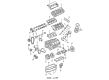
Buick Regal Oil Pan Part Number: 12512670
$186.28 MSRP: $276.52You Save: $90.24 (33%)Ships in 1-2 Business Days


Buick Regal Oil Pan Part Number: 12647251

Buick Regal Oil Pan Part Number: 555137
Buick Regal Oil Pan Part Number: 25536865

Buick Regal Oil Pan Part Number: 25522386
Buick Regal Oil Pan Part Number: 12676336

Buick Regal Oil Pan Part Number: 12563240
Buick Regal Oil Pan Part Number: 12353129
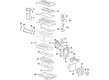
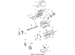
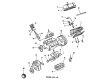
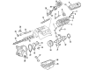
Buick Regal Oil Pan
Want to cut long-term maintenance and repair costs? Choose OEM Oil Pan. Those parts deliver top durability you can trust. On our site, you'll find a huge catalog of genuine Buick Regal parts. Prices are unbeatable, so you can keep more in your pocket. Every OEM Buick Regal Oil Pan includes a manufacturer's warranty. You can also get an easy return policy that keeps buying risk free. Fast delivery, get your car on the road quickly. It's simple to search, compare, and order. Stop guessing about quality or fit. Order today and save with parts that last.
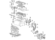
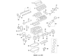
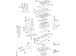
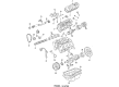
He Buick Regal Oil Pan plays a vital role in the automobile's lubrication system as its holds the oil in reserve and supplies it to lubricate the mechanical parts. Majority of Buick Regal cars come with the wet sump, whereby the oil pump pulls the oil from the pan with a pickup tube used in supplying the oil to the engine bearings and other parts before being recycled in the pan. In the past, Buick Regal engines may have included stamped steel oil pans, but in some modern models, cast aluminum reservoirs are used to increase the sturdiness and efficiency of the automobile. This design guarantees that the oil pan can contain sufficient quantity of the oil for different operational statuses typical of driving, to ensure efficiency and durability of the engine.
Buick Regal Oil Pan Parts and Q&A
- Q: How to replace the oil pan on Buick Regal?A:Start the Oil Pan replacement by disconnecting the negative Battery Cable then removing the fuel injector sight shield followed by disconnecting the intake air temperature (IAT) sensor electrical connector. The process starts with removing the Throttle Body air inlet duct in addition to the right and left Engine Mount struts. Set up the engine support fixture (J 28467-B) before lifting the vehicle with it. Start by removing the right exhaust manifold pipe stud nuts from the Catalytic Converter then drain all engine oil before you remove the Oil Filter. To reposition the wiring harness you need to detach power steering oil cooler pipe brackets from the frame and disconnect oil level sensor electrical connector and remove the oil level sensor wiring harness bolt. Start by removing the lower nuts from the engine mounts then lower the vehicle. The engine support fixture (J 28467-B) helps raise the engine before a second vehicle lift allows workers to remove the left and right Engine Mount bracket bolts, the right stabilizer link, and the right Ball Joint from the Steering Knuckle. Stop the frame with jack stands while you remove the right side frame bolts and loosen the left side frame bolts five turns prior to the frame lowering process. Extract first the Engine Mount and bracket from the frame before removing the torque converter covers. The first step before removing the Oil Pan is to disconnect the oil level sensor because damage is likely to occur. Begin the installation by removing both the Oil Pan bolts then the Oil Pan and the oil pump pipe screen assembly and the Oil Pan Gasket. All mating surfaces of the oil pump screen need cleaning along with the Oil Pan flanges and engine front cover and rear main bearing cap and threaded holes and Oil Pan rail. Place the Oil Pan Gasket and the oil pump pipe screen assembly on the vehicle before tightening the screen bolts to 15 nm (11 ft. Lbs.). We should install the Oil Pan using one drop of thread lock compound gm p/n 12345382 or equivalent on the cleaned Oil Pan bolts before tightening them at 14 nm (125 inch lbs.). After tightening the oil level sensor to 20 nm (15 ft. Lbs.), install the torque converter covers and secure the Engine Mount to the frame. After positioning the frame back to normal height, replace the frame bolts while the jack stands remain in place before removing them. Mount the right Ball Joint onto the Steering Knuckle along with the right stabilizer link before attaching the loose right and left Engine Mount bracket bolts to the engine. Secure these bolts at 102 nm (75 ft. Lbs.). Use the engine support fixture (J 28467-B) to lower the engine after lowering the vehicle. Lift the vehicle for a second time to bolt the Engine Mount lower nuts at 78 nm (58 ft. Lbs.) torque setting before installing the oil level sensor wiring harness and bolt with 10 nm (89 inch lbs.) torque. Next install the power steering oil cooler pipe brackets, right exhaust manifold pipe stud nuts, and connect the oil level sensor electrical connector. Tighten the attachments at 32 nm (24 ft. Lbs.). Place the engine Oil Filter then lower the vehicle and use j 28467-b to remove the engine support fixture after reinstalling the right and left Engine Mount struts. To complete the procedure install the air inlet duct then reconnect the iat sensor electrical connector before filling the crankcase with engine oil while reinstalling the fuel injector sight shield and connecting the negative Battery Cable and performing leak checks and wheel alignment measurements.

Related Buick Regal Parts
 Buick Regal Balance Shaft Bearing Set
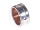
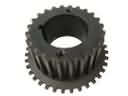 Buick Regal Crankshaft Gear
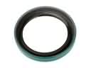 Buick Regal Crankshaft Seal
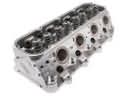 Buick Regal Cylinder Head
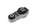 Buick Regal Engine Mount Torque Strut
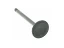 Buick Regal Intake Valve
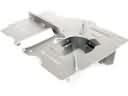 Buick Regal Oil Pan Baffle
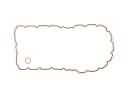 Buick Regal Oil Pan Gasket
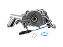 Buick Regal Oil Pump
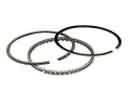 Buick Regal Piston Ring
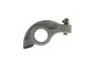 Buick Regal Rocker Arm
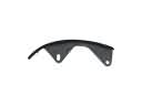 Buick Regal Timing Chain Guide