ChevyParts
My Garage
My Account
Cart
OEM Chevrolet Aveo Rod Bearing
Engine Connecting Rod Bearing- Select Vehicle by Model
- Select Vehicle by VIN
Select Vehicle by Model
orMake
Model
Year
Select Vehicle by VIN
For the most accurate results, select vehicle by your VIN (Vehicle Identification Number).
4 Rod Bearings found


Chevrolet Aveo Bearing Set Part Number: 93744930
$31.63 MSRP: $49.54You Save: $17.91 (37%)Ships in 1-3 Business Days


Chevrolet Aveo Bearing Set Part Number: 93742707
$34.87 MSRP: $54.61You Save: $19.74 (37%)Ships in 1-3 Business DaysChevrolet Aveo Bearing Set Part Number: 93744931
$29.11 MSRP: $45.60You Save: $16.49 (37%)Ships in 1-3 Business DaysChevrolet Aveo Bearing Set Part Number: 93742708
$31.52 MSRP: $49.38You Save: $17.86 (37%)Ships in 1-3 Business Days
Chevrolet Aveo Rod Bearing
Want to cut long-term maintenance and repair costs? Choose OEM Rod Bearing. Those parts deliver top durability you can trust. On our site, you'll find a huge catalog of genuine Chevrolet Aveo parts. Prices are unbeatable, so you can keep more in your pocket. Every OEM Chevrolet Aveo Rod Bearing includes a manufacturer's warranty. You can also get an easy return policy that keeps buying risk free. Fast delivery, get your car on the road quickly. It's simple to search, compare, and order. Stop guessing about quality or fit. Order today and save with parts that last.
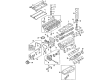
The Chevrolet Aveo Rod Bearing is certainly one of the most important the parts that can raise the quality of Chevrolet Aveo vehicles to a high level. Located within the region of the crankshaft and the connecting rods, the Rod Bearing helps to support the Rod and reduce friction in order to allow for a smooth rotation; a critical characteristic of most engine's efficient function. These Rod Bearings are available in bi-metal and tri-metal versions and are meant to be used on different Aveo models as well as on 1.2 L, 1.4 L, and 1.8 L Ecotec engines. The bi-metallic one has an aluminum alloy cladding component and a three-metal has a copper alloy component, which enhances its strength, making them appropriate for average and high quality. This variety is particularly important in the automotive market since the Chevrolet Aveo Rod Bearing is based on modern materials and design features: proprietary dry film coatings that increase wear resistance in conditions of high power consumption. This not only helps to improve the performance of the Chevrolet Aveo but also to a large extent helps in achieving its safety since the engine will also be intact. Since it is used in different generations of Aveo, the usage of the Rod Bearing is crucial to the operation of the vehicle offering durability. Chevrolet Aveo Rod Bearing is a tribute to the ever reliable products that Chevrolet has been rolling out in the market, thus putting their trust in the brand.
Chevrolet Aveo Rod Bearing Parts Questions & Experts Answers
- Q: How to replace the rod bearing on Chevrolet Aveo?A:To replace the Piston, connecting rod, and bearing, one is required to assemble the required tools: piston pin remover/installer set ( J 24086-B ), angle meter ( J 45059 ), and angular torque gage ( KM-470-B ). First, remove the Cylinder Head and manifolds for intake and exhaust, then the Oil Pan and oil suction pipe bolts to disconnect the oil suction pipe. Move the Piston to the bottom of the stroke and place a mark on the connecting rod cap for its position and remove the connecting rod cap bolts, cap, and lower connecting Rod Bearing. Then, remove the upper Piston connecting Rod Bearing and ridge ream the cylinder wall not to scratch it with sharp worn Piston rings. Depress the Piston and then apply the Piston Ring expander tool to expand and remove the Piston rings. Remove the Piston pin from the Piston and connecting rod by using the Piston pin remover/installer set (J 24086-B) and remove the Piston from the connecting rod. Align the notch of the Piston and the connecting rod to install the Piston pin guide, grease the Piston pin with clean oil, and feed it into the assembly using the Piston pin remover/installer set (J 24086-B). Choose new Piston rings, measure and adjust necessary the Piston Ring gap, and the assembly of Piston oil rings and compression rings in order. Space the oil ring gaps and apply clean engine oil to the cylinder wall and Piston Ring. Begin with a ring compressor and place a wood handle, then perform the installation of the Piston to the lower connecting rod end to avoid damaging the crankshaft journal. Mount the connecting rod cap and bearings then tighten connecting Rod Bearing cap bolts to 25 n.m (18 lb ft.) and further with the angle meter (J 45059) to an additional 30 degrees plus 15 degrees. Finally retighten the oil suction pipe and bolts to 10 n.m (89 lb in), retighten the pan and the Cylinder Head with intake and Exhaust Manifolds.

Related Chevrolet Aveo Parts
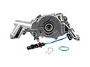 Chevrolet Aveo Oil Pump
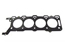 Chevrolet Aveo Head Gasket
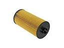 Chevrolet Aveo Oil Filter
 Chevrolet Aveo Camshaft
 Chevrolet Aveo Coolant Filter
 Chevrolet Aveo Crankshaft
 Chevrolet Aveo Crankshaft Pulley
 Chevrolet Aveo Dipstick
 Chevrolet Aveo Drain Plug
 Chevrolet Aveo Oil Drain Plug Gasket
 Chevrolet Aveo Rocker Shaft Spring Kit
 Chevrolet Aveo Timing Belt Idler Pulley