ChevyParts
My Garage
My Account
Cart
OEM Chevrolet Express 2500 Fuel Injector
Gas Injector- Select Vehicle by Model
- Select Vehicle by VIN
Select Vehicle by Model
orMake
Model
Year
Select Vehicle by VIN
For the most accurate results, select vehicle by your VIN (Vehicle Identification Number).
16 Fuel Injectors found


Chevrolet Express 2500 Injector Part Number: 12710481
$69.60 MSRP: $141.40You Save: $71.80 (51%)

Chevrolet Express 2500 Injector Part Number: 12613412
$41.08 MSRP: $83.44You Save: $42.36 (51%)Ships in 1-2 Business Days
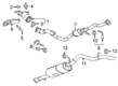
Chevrolet Express 2500 Muffler Part Number: 55594509
$338.47 MSRP: $687.46You Save: $348.99 (51%)
Chevrolet Express 2500 Injector Part Number: 55504598
$274.55 MSRP: $492.46You Save: $217.91 (45%)
Chevrolet Express 2500 Injector Part Number: 19421333
$106.16 MSRP: $215.60You Save: $109.44 (51%)
Chevrolet Express 2500 Injector Part Number: 97780474
$486.29 MSRP: $963.93You Save: $477.64 (50%)Ships in 1-3 Business DaysChevrolet Express 2500 Injector Part Number: 88894353
$120.24 MSRP: $244.20You Save: $123.96 (51%)Ships in 1-2 Business Days
Chevrolet Express 2500 Injector Part Number: 17113698
$112.36 MSRP: $228.20You Save: $115.84 (51%)Chevrolet Express 2500 Injector Part Number: 12613411
$81.23 MSRP: $172.82You Save: $91.59 (53%)Ships in 1-2 Business Days
Chevrolet Express 2500 Injector Part Number: 19210900
$399.51 MSRP: $737.27You Save: $337.76 (46%)Ships in 1-2 Business Days


Chevrolet Express 2500 Injector Part Number: 12684125
Chevrolet Express 2500 Injector Part Number: 98002368
Chevrolet Express 2500 Injector Part Number: 17091432

Chevrolet Express 2500 Injection Nozzle Part Number: 12458122
Chevrolet Express 2500 Injector Part Number: 12720120
$104.03 MSRP: $162.94You Save: $58.91 (37%)Chevrolet Express 2500 Injector Part Number: 12720121
$104.03 MSRP: $162.94You Save: $58.91 (37%)
Chevrolet Express 2500 Fuel Injector
Want to cut long-term maintenance and repair costs? Choose OEM Fuel Injector. Those parts deliver top durability you can trust. On our site, you'll find a huge catalog of genuine Chevrolet Express 2500 parts. Prices are unbeatable, so you can keep more in your pocket. Every OEM Chevrolet Express 2500 Fuel Injector includes a manufacturer's warranty. You can also get an easy return policy that keeps buying risk free. Fast delivery, get your car on the road quickly. It's simple to search, compare, and order. Stop guessing about quality or fit. Order today and save with parts that last.
Chevrolet Express 2500 Fuel Injector Parts and Q&A
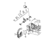
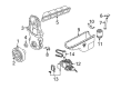
- Q: How to replace the fuel injector on Chevrolet Express 2500?A:The fuel meter body assembly needs removal before proceeding with Fuel Injector replacement. The injector assembly retainer and injector retainer lock nuts need to be uninstall while paying attention to protect electrical connector terminals before you remove the fuel injectors as they should be treated as one complete assembly. Cleaning the electrical fuel injectors remains discouraged because they need to stay away from all types of solvents and the prevention of damage requires they stay dry. A small tip punch should be used to push down between the injector terminals when pulling the poppet nozzle tube downward for injector removal. A proper installation process requires calibration of each injector at its designated flow rate followed by the correct installment of the injector complied with the application type. The new injector o-ring seals need lubrication using clean engine oil before receiving their proper placement on the injector assembly . After installing the Fuel Injector assembly into its socket position the system with the injector assembly retainer together with the injector retainer lock nuts at 3.0 n.m (27 lb in). Reinstall the fuel meter body assembly as the last step of the procedure.
- Q: How to clean and service the fuel injector on Chevrolet Express 2500?A:A proper start for Fuel Injector cleaning involves first loosening the fuel fill cap to reduce Fuel Tank vapor pressure. Begin by removing the positive crankcase ventilation (PCV) clean air tube from the air inlet duct after which you should detach the resonator along with the air inlet duct from the Throttle Body. Detach both the Brake Booster Vacuum Hose with its connector at the Intake Manifold and then unplug the electrical connector on the central sequential fuel injection (CSFI) fuel metering body. At the Distributor Cap remove Spark Plug Wires from cylinders 1, 3 and 5. Then take out the fuel line bolt at the rear side of the Intake Manifold. You must drain all pressure from the fuel system first before you can take out the fuel pipes from the metering body by unfastening the fuel pipe nuts and clamp from their position. Push the j 44466-12 and j 44466-13 into the metering body before tightening the process while validating the correct fuel pipe arrangement of o-rings, washers, and spacers. Proceed by installing the j 44466-11 followed by clamping and tight installation of the j 44466-13 onto the fuel pipe. Use the j 41413 to shut down tank valve pressure before taking out the regulator assembly. Install the j 44466-10 onto the j 41413 tank body. Connect the j 44466-10 hose to the j 44466-12 while installing the metering body components including the j 39021, j 39021-210 and j 39021-301 to the electrical connector. Adjust the amperage switch on the j 39021 to 0.5 amps. Open the valves on the tank and the j 44466-10 to achieve fuel system pressurization which should maintain at least 150 psi. You should use the j 39021 to open one injector and monitor the gauge pressure which demonstrates proper injector functionality before proceeding to other injectors. Confirm all the injectors operate correctly before stopping the j 41413 tank pressure valve and bleeding pressure off at j 44466-10. Install the fresh air tube of pcv before removing the j 44466-10 from its connections to the j 44466-12 and j 41413. Remove the j 39021-301 and j 39021-210 and j 39021 from the metering body. The procedure now involves connecting the vehicle electrical connector followed by installing the Brake Booster Vacuum Hose and ignition wires before attaching the resonator and air intake duct. Begin by operating the j 38500-a while making sure to close its bottom valve then fill the canister with gm p/n 1050002 top engine cleaner (Canadian P/N 992872) followed by regular unleaded gasoline. After which suspend j 38500-a under the hood. Thread the hose from j 38500-a to the service port of j 44466-12 and proceed by opening the j 38500-a bottom valve and linking a shop air source while setting its regulator to 75 psi. Once the canister empties out at stall time stop shop air. Detach the j 44466-12 hose and remove pcv air tube followed by resonator and wires before bleeding j 44466-12. Begin the procedures by taking out j 44466-13 and j 44466-12 from the metering body then remove j 44466-13 , clamp , and j 44466-11 from the fuel pipe. Reinstall the fuel pipe to the metering body while placing all o-rings washers and spacers properly in position followed by nut and clamp installation at 3 n.m (27 lb ft). Treat the fuel pipe bolt threads with thread lock gm p/n 12345382 (Canadian P/N 10953489) then place and rotate the bolt to 6 n.m (53 lb ft). Reposition first the Brake Booster Vacuum Hose and then the resonator followed by the air inlet duct before installing the pcv clean air tube and ignition wires. A dose of 1 ounce of port Fuel Injector cleaner gm p/n 12345104 (Canadian P/N 12345515) must be added to each gallon of gasoline in the Fuel Tank but the customer should finish the rest of the bottle during the next fill-up. Start the engine while keeping the Fuel Tank filler cap hand-tightened for leak checking. Scribers should use a tech ii scan tool to inspect powertrain dtc codes that have been stored and decide whether to advocate a new fuel brand to their customer.


Related Chevrolet Express 2500 Parts
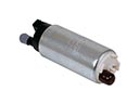 Chevrolet Express 2500 Fuel Pump
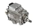 Chevrolet Express 2500 Fuel Injection Pump
 Chevrolet Express 2500 Fuel Injector O-Ring
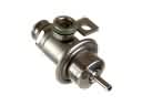 Chevrolet Express 2500 Fuel Pressure Regulator
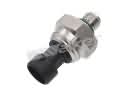 Chevrolet Express 2500 Fuel Pressure Sensor
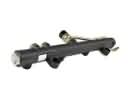 Chevrolet Express 2500 Fuel Rail
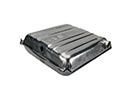 Chevrolet Express 2500 Fuel Tank
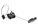 Chevrolet Express 2500 Fuel Tank Sending Unit
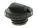 Chevrolet Express 2500 Gas Cap
 Chevrolet Express 2500 Idle Control Valve
 Chevrolet Express 2500 Throttle Body Gasket
 Chevrolet Express 2500 Vapor Pressure Sensor