ChevyParts
My Garage
My Account
Cart
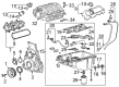
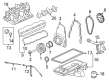
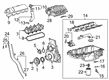
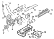
OEM GMC Yukon Intake Manifold
Engine Intake Manifold- Select Vehicle by Model
- Select Vehicle by VIN
Select Vehicle by Model
orMake
Model
Year
Select Vehicle by VIN
For the most accurate results, select vehicle by your VIN (Vehicle Identification Number).
17 Intake Manifolds found


GMC Yukon Intake Manifold Part Number: 12639087
$153.81 MSRP: $261.86You Save: $108.05 (42%)Ships in 1-2 Business Days

GMC Yukon Intake Manifold Part Number: 12623417
$245.09 MSRP: $420.93You Save: $175.84 (42%)Ships in 1-2 Business Days


GMC Yukon Intake Manifold Part Number: 12620308
$216.35 MSRP: $351.12You Save: $134.77 (39%)
GMC Yukon Intake Manifold Part Number: 40009057
$126.75 MSRP: $215.75You Save: $89.00 (42%)Ships in 1-3 Business Days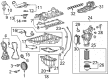
GMC Yukon Intake Manifold Part Number: 12638038
$224.44 MSRP: $382.10You Save: $157.66 (42%)Ships in 1-2 Business Days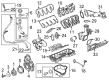
GMC Yukon Intake Manifold Part Number: 12597600
$161.11 MSRP: $388.46You Save: $227.35 (59%)Ships in 1-2 Business Days


GMC Yukon Manifold Part Number: 17113697


GMC Yukon Intake Manifold, Lower Part Number: 17113201


GMC Yukon Intake Manifold Part Number: 17113541


GMC Yukon Intake Manifold Part Number: 12580678
$231.11 MSRP: $363.63You Save: $132.52 (37%)


GMC Yukon Intake Manifold Part Number: 12580420
$187.90 MSRP: $295.65You Save: $107.75 (37%)GMC Yukon Intake Manifold Part Number: 89017365

GMC Yukon Intake Manifold Part Number: 19418186

GMC Yukon Manifold Part Number: 12556527
GMC Yukon Manifold Part Number: 12556526

GMC Yukon Intake Manifold Part Number: 12620307
GMC Yukon Intake Manifold Part Number: 10166135
GMC Yukon Intake Manifold
Want to cut long-term maintenance and repair costs? Choose OEM Intake Manifold. Those parts deliver top durability you can trust. On our site, you'll find a huge catalog of genuine GMC Yukon parts. Prices are unbeatable, so you can keep more in your pocket. Every OEM GMC Yukon Intake Manifold includes a manufacturer's warranty. You can also get an easy return policy that keeps buying risk free. Fast delivery, get your car on the road quickly. It's simple to search, compare, and order. Stop guessing about quality or fit. Order today and save with parts that last.
The Intake Manifold in GMC Yukon operates the circulation of air or air/fuel mixture to the engine cylinders thus regulating the power and efficiency. Usually, intake manifold is made from the light plastic as it provides balanced distribution of air and fuel which results in improved combustion. Some models include two halves of the block that are bolted together with gaskets or coolant channels and thermostat bosses for control of the engine. An performance manifold can increase horsepower and torque many times more than stock, especially when teamed with engine changes. Linked Variable Length Intake Manifold enhances the power or torque and fuel efficiency by controlling the speed and pressure of airflow according to the load conditions of the engine; thus, applying the Variable Length Intake Manifold creates more powerful engines.
GMC Yukon Intake Manifold Parts and Q&A
- Q: How to replace the intake manifold on GMC Yukon?A:High voltage service disconnect and disconnection of the battery ground cable must both occur before starting the Intake Manifold replacement. The installment of manifold replacement demands the removal of three components: air cleaner outlet duct, engine harness retainer nut and engine harness retainer from stud and locator pin. The engine harness electrical connectors must be disconnected from seven crucial components: evap canister purge solenoid, manifold absolute pressure sensor and ignition coil harness in addition to left side Fuel Injectors, throttle actuator and right side fuel injectors and engine Coolant Temperature Sensor. Unplug the generator control module electrical connector while using zip ties to fasten the engine harness branches above the work area. You must separate the evap canister purge tube from its quick connector as well as the fuel feed tube from its quick connector. First remove the positive crankcase ventilation (PCV) hose followed by loosening the Intake Manifold bolts (512) until you can extract the Intake Manifold (500). Protect the cylinder head passages while discarding and removing new Intake Manifold gaskets (514). Clean and inspect the Intake Manifold. Start by removing the upper Intake Manifold cover nut and the upper Intake Manifold cover then remove the MAP Sensor retainer and the MAP Sensor and discard the MAP Sensor seal. First disconnect the fast release of the evap tube at the Intake Manifold then release the retainer for the evap canister purge solenoid while removing the Throttle Body together with its gasket. Remove the Fuel Rail bolts before lifting the rail evenly to extract all injectors. The lower o-ring seals on the fuel injectors need immediate disposal. Begin by applying clean engine oil to new Fuel Injector lower o-ring seals before installing them onto the injectors. Then fasten the Fuel Rail to 10 nm (89 lb in) torque. Place a fresh Throttle Body Gasket onto the Throttle Body assembly with bolts/nuts secured to 10 nm torque (89 lb in). After installation of the evap tube and purge solenoid you must secure the solenoid to the Fuel Rail bracket before you connect the evap tube quick connect fitting at the Intake Manifold. Use engine oil to lubricate the MAP Sensor seal after which you should install the sensor along with a fresh seal and fasten it with the retainer. Begin by tightening the upper Intake Manifold cover and nut before adding new Intake Manifold gaskets (514) and removing the cylinder head passage covers to install the Intake Manifold (500). Apply a 5 mm (0.20 in) band of threadlock gm p/n 12345382 (Canadian P/N 10953489) to the Intake Manifold bolts (512) threads, install the bolts finger tight, and tighten them to specifications: the bolt torques start at 5 nm (44 lb in) during the first stage then finish at 10 nm (89 lb in). Position the pcv hose before connecting the fuel feed line quick connect fitting to the Fuel Rail as well as the evap canister purge tube quick connect fitting to the evap canister purge solenoid. Attach the engine harness electrical connector to the ect sensor before installing the engine harness clip to the generator bracket and tightening the bolt to 9 nm (80 lb in). The installation requires connecting the generator control module electrical connector along with the engine harness electrical connectors to the right side fuel injectors before installing the engine harness clip onto the ignition coil bracket stud. Route the engine harness electrical connectors for left side fuel injectors and ignition coil harness electrical connector before placing the cpa retainer. The engine wiring harness electrical connector should be attached to both MAP Sensor and evap canister purge solenoid before the engine harness retainer can be installed with a nut torque of 5 nm (44 lb in). Complete the high voltage service connect after reinstalling the air cleaner outlet duct and reattaching the battery ground cable.

Related GMC Yukon Parts
 GMC Yukon Air Filter
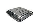 GMC Yukon Fuel Tank
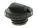 GMC Yukon Gas Cap
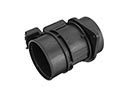 GMC Yukon Mass Air Flow Sensor
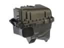 GMC Yukon Air Filter Box
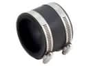 GMC Yukon Air Intake Coupling
 GMC Yukon Crankcase Breather Hose
 GMC Yukon Fuel Filler Housing
 GMC Yukon Fuel Pump Seal
 GMC Yukon Fuel Tank Strap
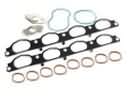 GMC Yukon Intake Manifold Gasket
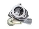 GMC Yukon Turbocharger