ChevyParts
My Garage
My Account
Cart
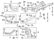
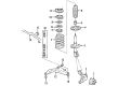
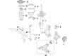
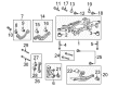
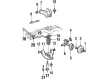
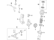
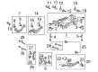
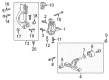
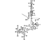
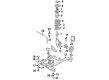
OEM Buick Control Arm
Suspension Arm- Select Vehicle by Model
- Select Vehicle by VIN
Select Vehicle by Model
orMake
Model
Year
Select Vehicle by VIN
For the most accurate results, select vehicle by your VIN (Vehicle Identification Number).
157 Control Arms found


Buick Control Arm, Rear Driver Side Part Number: 22927292
$126.72 MSRP: $215.74You Save: $89.02 (42%)Ships in 1-2 Business DaysProduct Specifications- Other Name: Arm Assembly-Rear Suspension Control; Suspension Trailing Arm Bushing; Suspension Trailing Arm; Trailing Arm; Front Upper Control Arm; Arm, Rear Axle Control Arm
- Position: Rear Driver Side
- Replaces: 13219145


Buick Lower Control Arm, Passenger Side Part Number: 22947663
$175.65 MSRP: $299.06You Save: $123.41 (42%)Ships in 1-2 Business DaysProduct Specifications- Other Name: Arm, Steering Knuckle Control Arm and Ball Joint Assembly; Suspension Control Arm Assembly.; Arm, Steering Knuckle Lower Control
- Position: Passenger Side
- Replaces: 10328897, 10303057, 10348612, 10287709, 10328899, 10301553, 15293664, 15293661, 10301555, 10291504, 10348610, 15293666, 20977506, 25853334


Buick Lower Control Arm, Driver Side Part Number: 84107269
$135.55 MSRP: $218.41You Save: $82.86 (38%)Product Specifications- Other Name: Arm, Steering Knuckle Upper & Lower Control; Control Arm
- Position: Driver Side
- Replaced by: 84376575


Buick Upper Control Arm, Rear Driver Side Part Number: 23216530
$136.93 MSRP: $236.63You Save: $99.70 (43%)Ships in 1-2 Business DaysProduct Specifications- Other Name: Arm, Rear Axle Control Arm; Suspension Control Arm; Rear Upper Control Arm; Control Arm
- Position: Rear Driver Side
- Replaces: 20921466


Buick Upper Control Arm, Rear Driver Side Part Number: 20900531
$108.12 MSRP: $188.43You Save: $80.31 (43%)Ships in 1-2 Business DaysProduct Specifications- Other Name: Arm, Rear Axle Control Arm; Suspension Control Arm; Rear Upper Control Arm; Control Arm
- Position: Rear Driver Side

Buick Lower Control Arm, Rear Passenger Side Part Number: 23214431
$283.34 MSRP: $456.59You Save: $173.25 (38%)Ships in 1-2 Business DaysProduct Specifications- Other Name: Arm, Rear Axle Control Arm; Rear Lower Control Arm; Control Arm
- Position: Rear Passenger Side
- Replaces: 20921463, 23182016

Buick Control Arm, Front Upper Passenger Side Part Number: 19416899
$219.74 MSRP: $377.38You Save: $157.64 (42%)Ships in 1-2 Business DaysProduct Specifications- Other Name: Arm Kit, Front Upper Control; Upper Control Arm; Arm Kit, Steering Knuckle Upper & Lower Control; Arm, Steering Knuckle Upper & Lower Control
- Position: Front Upper Passenger Side
- Replaces: 12376266, 19133654, 12543948, 12546748

Buick Lower Control Arm, Passenger Side Part Number: 84248220
$211.19 MSRP: $362.71You Save: $151.52 (42%)Ships in 1-3 Business DaysProduct Specifications- Other Name: Arm, Steering Knuckle Upper & Lower Control
- Position: Passenger Side
- Replaces: 20835937, 22854826, 84248217, 23354432
Buick Upper Control Arm, Rear Passenger Side Part Number: 13318345
$91.53 MSRP: $150.78You Save: $59.25 (40%)Ships in 1-2 Business DaysProduct Specifications- Other Name: Arm, Rear Axle Control Arm; Rear Upper Control Arm
- Position: Rear Passenger Side

Buick Shaft Assembly, Upper Part Number: 12385857
$51.62 MSRP: $103.65You Save: $52.03 (51%)Product Specifications- Other Name: Shaft Kit, Steering Knuckle Upper Control Arm; Control Arm Shaft Kit; Control Arm Shaft; Upper Shaft; Shaft; Shaft Kit, Upper Control Arm Shaft
- Position: Upper

Buick Upper Control Arm, Rear Driver Side Part Number: 84178160
$99.55 MSRP: $162.94You Save: $63.39 (39%)Product Specifications- Other Name: Arm, Rear Axle Control Arm; Lateral Link; Lateral Arm; Rear Upper Control Arm; Control Arm
- Position: Rear Driver Side
- Replaces: 22830017, 13230592
Buick Lower Control Arm, Driver Side Part Number: 84248221
$216.80 MSRP: $424.46You Save: $207.66 (49%)Ships in 1-2 Business DaysProduct Specifications- Other Name: Arm, Steering Knuckle Upper & Lower Control
- Position: Driver Side
- Replaces: 20835936, 23354433, 84248216, 22854825
Buick Upper Control Arm, Rear Passenger Side Part Number: 23216531
$136.93 MSRP: $236.63You Save: $99.70 (43%)Ships in 1-2 Business DaysProduct Specifications- Other Name: Arm, Rear Axle Control Arm; Suspension Control Arm; Rear Upper Control Arm; Control Arm
- Position: Rear Passenger Side
- Replaces: 20921469
Buick Lower Control Arm, Rear Driver Side Part Number: 23214430
$283.34 MSRP: $456.60You Save: $173.26 (38%)Ships in 1-2 Business DaysProduct Specifications- Other Name: Arm, Rear Axle Control Arm; Rear Lower Control Arm; Control Arm
- Position: Rear Driver Side
- Replaces: 23182015, 20921462
Buick Upper Control Arm, Rear Passenger Side Part Number: 20900532
$107.64 MSRP: $186.02You Save: $78.38 (43%)Ships in 1-2 Business DaysProduct Specifications- Other Name: Arm, Rear Axle Control Arm; Suspension Control Arm; Rear Upper Control Arm; Control Arm
- Position: Rear Passenger Side
Buick Lower Control Arm, Driver Side Part Number: 84376575
$136.78 MSRP: $218.41You Save: $81.63 (38%)Product Specifications- Other Name: Arm, Steering Knuckle Upper & Lower Control; Control Arm
- Position: Driver Side
- Replaces: 84107269

Buick Lower Control Arm, Driver Side Part Number: 22905355
Product Specifications- Other Name: Arm, Steering Knuckle Upper & Lower Control
- Position: Driver Side
- Replaces: 22828443

Buick Control Arm, Driver Side Part Number: 10249747
Product Specifications- Other Name: Arm, Steering Knuckle Upper & Lower Control; Lower Control Arm; Arm, Steering Knuckle Lower Control
- Position: Driver Side
Buick Control Arm, Passenger Side Part Number: 10249748
Product Specifications- Other Name: Arm, Steering Knuckle Upper & Lower Control; Lower Control Arm; Arm, Steering Knuckle Lower Control
- Position: Passenger Side

Buick Control Arm, Driver Side Part Number: 10114663
Product Specifications- Other Name: Arm, Steering Knuckle Upper & Lower Control; Suspension Control Arm; Lower Control Arm; Arm, Steering Knuckle Lower Control
- Position: Driver Side
| Page 1 of 8 |Next >
1-20 of 157 Results
Buick Control Arm
Want to cut long-term maintenance and repair costs? Choose OEM Control Arm. Those parts deliver top durability you can trust. On our site, you'll find a huge catalog of genuine Buick parts. Prices are unbeatable, so you can keep more in your pocket. Every OEM Buick Control Arm includes a manufacturer's warranty. You can also get an easy return policy that keeps buying risk free. Fast delivery, get your car on the road quickly. It's simple to search, compare, and order. Stop guessing about quality or fit. Order today and save with parts that last.
Buick Control Arm Parts Questions & Experts Answers
- Q: How to replace the lower control arm on Buick Park Avenue?A:In order to replace the lower Control Arm, start with using the j 43828 Ball Joint separator (J 43828) that will allow the opportunity to separate the Ball Joint away from the knuckle and make sure that the vehicle is properly and safely raised and supported. Remove the tire and the wheel, and the stabilizer shaft link. After that, remove the cotter pin from the lower Ball Joint and loosen the lower Ball Joint retaining nut from a ball-stud. Take caution and avoid over extension of the tri-pot joints, and use drives axle joint seal protectors to protect the joints from damage. But after removing the lower Ball Joint from the steering knuckle from front to take a lower bottom Ball Joint retaining nut then a remove lower Control Arm mounting bolts and nuts to remove lower Control Arm from the frame. To install, align the lower Control Arm to the frame but do not tighten the Control Arm nuts at first; support the weight of the vehicle by the control arms to reach the proper trim heights before attaching the lower Control Arm bolts and nuts. Install the lower Ball Joint and retaining nut to the steering knuckle by tightening the retaining nut to 10 nm (88 inch lbs.) plus 150 degrees and make sure that the two flats are tightened to a minimum of 55 nm (41 ft. Lbs.) to align the cotter pin slot. Replace the cotter pin, reattach stabilizer shaft link, then put the tire n wheel back on before lowering the vehicle. Finally, tighten nut of control arms in a sequence starting with the rear mounting bolts of 158 nm (117 ft. Lbs.), and then front mounting nut 126 nm (93 ft. Lbs.), and inspecting the trim height.
- Q: How to service and repair the front lower control arm on Buick LeSabre?A:To properly service and repair the front lower Control Arm, first, lift and hold the vehicle, second, uninstall the tire and the wheel, third, uninstall the stabilizer shaft link. Then discard the cotter pin and loosen the honey nut of lower Ball Joint from the pollution, while avoiding over extension of the tri- pot joints that might result in loss of separation of internal components and failure of the joints. Separate the lower Ball Joint from the Steering Knuckle using the j43828 Ball Joint separator (J43828), and remove the lower Control Arm of the Steering Knuckle, followed by the lower Ball Joint retaining nut, the lower Control Arm mounting bolts and nuts, and remove the lower Ball Joint from the frame. For laying, fix the lower Control Arm to the frame but do not tighten the nuts of lower Control Arm takes but first; support the weight of the vehicle with the control arms so as to attain the design trim heights before fitting the lower bolts, the Control Arm, and the nuts. Replace the opposite Ball Joint and nut to the Steering Knuckle and tighten the lower Ball Joint scoring nut to 10 nm (88 in. Lbs.), the two flats to a minimum of 55 nm (41 ft. Lbs.) to align the cotter pin slot and the cotter pin. Replace the stabilizer shaft link, tire, and wheel, lower the vehicle and perform trim height check. Lastly, tighten the Control Arm bolts in the following order: rear mounting bolt 158 nm (117 ft. Lbs) and the front mounting nut 158 nm (117 ft. Lbs).
- Q: How to replace the rear axle lower control arm on Buick Rainier?A:Rear axle lower control arm replacement requires users to lift the vehicle while securing both components at specified D-height levels per Trim Height Specifications. Affiliated vehicles with air suspension need to experience air suspension system depressurization. Begin by removing the rear axle lower control arm through this process: disconnect the mounting nut and bolt from the axle then loosen the frame mounting nut and bolt to extract the control arm. Installation begins with the lower control arm followed by mounting the rear axle to the frame with its mounting nut and bolt and finally attaching it to the axle with its mounting bolt and nut. Secure the lower control arm mounting bolts to 100 Nm while following the Fastener Notice in Service Precautions instructions. Afterwards lower the vehicle by removing the rear axle support.


Related Buick Parts
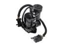 Buick Air Suspension Compressor
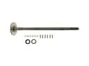 Buick Axle Shaft
 Buick Control Arm Bracket
 Buick Lateral Link
 Buick Leaf Spring
 Buick Ride Height Sensor
 Buick Shock Absorber
 Buick Shock and Strut Boot
 Buick Steering Knuckle
 Buick Strut Bearing
 Buick Suspension Strut Rod
 Buick Trailing Arm Bushing