ChevyParts
My Garage
My Account
Cart
OEM GMC Fuel Rail
Engine Fuel Rail- Select Vehicle by Model
- Select Vehicle by VIN
Select Vehicle by Model
orMake
Model
Year
Select Vehicle by VIN
For the most accurate results, select vehicle by your VIN (Vehicle Identification Number).
77 Fuel Rails found


GMC Fuel Rail Part Number: 12678991
$222.60 MSRP: $452.12You Save: $229.52 (51%)Ships in 1-2 Business DaysProduct Specifications- Other Name: Rail, Fuel Injection
- Replaced by: 12686810


GMC Fuel Rail Part Number: 97361353
$336.68 MSRP: $683.83You Save: $347.15 (51%)Product Specifications- Other Name: Rail, Fuel Injection


GMC Fuel Rail Part Number: 12623365
$163.31 MSRP: $295.58You Save: $132.27 (45%)Ships in 1-2 Business DaysProduct Specifications- Other Name: Rail, Fuel Injection

GMC Fuel Rail Part Number: 12621668
$198.77 MSRP: $359.76You Save: $160.99 (45%)Ships in 1-2 Business DaysProduct Specifications- Other Name: Rail, Fuel Injection
- Replaced by: 12660709

GMC Fuel Rail Part Number: 12654644
$251.84 MSRP: $455.82You Save: $203.98 (45%)Ships in 1-3 Business DaysProduct Specifications- Other Name: Rail, Fuel Injection
- Replaces: 12627090

GMC Fuel Rail Part Number: 12621663
$236.37 MSRP: $427.82You Save: $191.45 (45%)Ships in 1-2 Business DaysProduct Specifications- Other Name: Rail, Fuel Injection
- Replaces: 12621561
GMC Fuel Rail Part Number: 55510921
$459.87 MSRP: $828.60You Save: $368.73 (45%)Ships in 1-3 Business DaysProduct Specifications- Other Name: Rail Assembly-High Pressure Diesel Fuel Injection; Rail, Fuel Injection
- Replaces: 55484516
GMC Fuel Rail Part Number: 12733958
$105.75 MSRP: $188.84You Save: $83.09 (44%)Ships in 1-2 Business DaysProduct Specifications- Other Name: Rail, Fuel Injection
GMC Fuel Rail Part Number: 25205429
$111.78 MSRP: $199.60You Save: $87.82 (44%)Ships in 1-2 Business DaysProduct Specifications- Other Name: Rail Assembly-Direct Fuel Injection Fuel; Rail, Fuel Injection

GMC Fuel Rail Part Number: 12701658
$183.80 MSRP: $329.68You Save: $145.88 (45%)Ships in 1-3 Business DaysProduct Specifications- Other Name: Rail, Fuel Injection
- Replaces: 12668188
GMC Fuel Rail Part Number: 12688001
$98.97 MSRP: $176.74You Save: $77.77 (44%)Ships in 1-3 Business DaysProduct Specifications- Other Name: Rail, Fuel Injection
- Replaced by: 12729341
GMC Fuel Rail Part Number: 12729341
$98.97 MSRP: $176.74You Save: $77.77 (44%)Ships in 1-3 Business DaysProduct Specifications- Other Name: Rail, Fuel Injection
- Replaces: 12688001
GMC Fuel Rail Part Number: 12709433
$125.97 MSRP: $225.96You Save: $99.99 (45%)Product Specifications- Other Name: Rail, Fuel Injection
- Replaces: 12671078
GMC Fuel Rail Part Number: 89018110
$188.56 MSRP: $341.28You Save: $152.72 (45%)Ships in 1-2 Business DaysProduct Specifications- Other Name: Rail Kit, Fuel Injection
- Replaced by: 12621662
GMC Fuel Rail Part Number: 12621665
$184.53 MSRP: $374.78You Save: $190.25 (51%)Ships in 1-2 Business DaysProduct Specifications- Other Name: Rail, Fuel Injection
- Replaced by: 12660710
GMC Fuel Rail Part Number: 40009114
$134.63 MSRP: $273.44You Save: $138.81 (51%)Product Specifications- Other Name: Rail Assembly-High Pressure Diesel Fuel Injection; Rail, Fuel Injection
GMC Fuel Rail Part Number: 55505909
$198.35 MSRP: $355.78You Save: $157.43 (45%)Ships in 1-3 Business DaysProduct Specifications- Other Name: Rail Assembly-High Pressure Diesel Fuel Injection; Rail, Fuel Injection
GMC Fuel Rail Part Number: 12707885
$107.92 MSRP: $192.72You Save: $84.80 (44%)Ships in 1-2 Business DaysProduct Specifications- Other Name: Rail-Fuel Injection Fuel *Must Use Together With
- Replaced by: 12729463
GMC Fuel Rail Part Number: 12719353
$128.28 MSRP: $229.32You Save: $101.04 (45%)Ships in 1-3 Business DaysProduct Specifications- Other Name: Rail, Fuel Injection
GMC Fuel Rail Part Number: 12706269
$125.35 MSRP: $197.22You Save: $71.87 (37%)Ships in 1-3 Business DaysProduct Specifications- Other Name: Rail, Fuel Injection
- Replaces: 12671079
| Page 1 of 4 |Next >
1-20 of 77 Results
GMC Fuel Rail
Want to cut long-term maintenance and repair costs? Choose OEM Fuel Rail. Those parts deliver top durability you can trust. On our site, you'll find a huge catalog of genuine GMC parts. Prices are unbeatable, so you can keep more in your pocket. Every OEM GMC Fuel Rail includes a manufacturer's warranty. You can also get an easy return policy that keeps buying risk free. Fast delivery, get your car on the road quickly. It's simple to search, compare, and order. Stop guessing about quality or fit. Order today and save with parts that last.
GMC Fuel Rail Parts Questions & Experts Answers
- Q: What are the steps involved in servicing the L59 E85 fuel rail on GMC Sierra 1500?A:Fuel delivery through the l59 e85 Fuel Rail needs e85 denso fuel injectors which require special maintenance procedures because it works with fuel containing up to 85 percent ethanol. You should start by reducing fuel system pressure then unfastening the wire harness bracket nut. Disconnect first the electrical connector for evaporative emission (EVAP) purge solenoid followed by generator and then manifold absolute pressure (MAP) sensor and knock sensor connectors. The knock sensor harness connector should be removed from the intake manifold while also taking away the cpa retainer and main coil and Fuel Injector connectors. Next step requires dissolving the harness clips from the Fuel Rail area while moving the upper engine wire harness into position. Preventing connector damage requires that you refrain from using pliers to disconnect multec(R) 2 Fuel Injector connectors. The reassembly requires marking the connectors first before using the cpa retainer to lift one click and pushing the tab on each connector while disconnecting them sequentially. The procedure requiresmitters to start by disconnecting the fuel pressure regulator vacuum line, the pcv hose and the fuel feed and return pipes (1, 2) before unbolting the Fuel Rail. Before removing the Fuel Rail assembly users must carefully pull out the component to protect both injector electrical connector terminals and spray tips and apply caps on open fittings to block contamination. Spray type engine cleaners should be used on the Fuel Rail assembly when needed and new Fuel Injector lower o-ring seals require clean engine oil to lubricate before they are installed. The Fuel Rail installation requires threadlocking gm p/n 12345382 or its canadian equivalent p/n 10953489 to be applied on Fuel Rail bolts before tight installation to 10 n.m (89 lb in). After reattaching the pcv hose you must hook up the fuel pressure regulator vacuum line alongside the fuel feed and return pipes (1, 2). The engine wire harness should be positioned before reattaching the Fuel Injector electrical connectors properly. After reconnecting the main coil and fuel injectors the harness clips must be installed onto the Fuel Rail while also installing the cpa retainers. Reconnect the MAP Sensor connector with the knock sensor connector to the intake manifold along with the evap purge solenoid electrical connector and the generator electrical connector. Insert the wire harness bracket nut before fastening it with 5 n.m (44 lb in) torque then secure the fuel fill cap and fasten the negative Battery Cable. Perform a leak examination using this sequence of check: turn ignition on for 2 seconds followed by off for 10 seconds and then turn on once more to detect fuel leaks.
- Q: How to replace the Fuel Injection Fuel Rail Assembly for Bank 2 (LLT) (3.6L) on GMC Acadia?A:The beginning step to replace the fuel injection Fuel Rail assembly for bank 2 (LLT) (3.6L) consists of using ch-48027 or without it to relieve fuel system pressure. The next procedure involves removing the fuel pipe shield in addition to the high pressure fuel sensor and Fuel Rail crossover pipe before discarding the crossover pipe. Begin by removing the Fuel Rail bolts then lift the bank 2 Fuel Rail from the engine while paying attention to the rear section which will make removal simpler. The direct Fuel Injector hold down clamps need disposal because direct fuel injectors require rebuild whenever removal occurs from the Fuel Rail or cylinder head. The next step involves Fuel Injector rebuild after the removal of the Fuel Rail. Secure the rebuilt direct fuel injectors into their corresponding cylinder heads positions using newly installed hold down clamps. Silicon-free engine oil gm p/n 12345610 (Canadian P/N 9931930) or equivalent should be used to lubricate Fuel Injector cups on the new Fuel Rail before placing the front end over the front injector then rotating the rear down. Begin by screwing the outer Fuel Rail bolts and then proceed to install inner bolts before conducting hand tightening. Sequence the bank 1 Fuel Rail bolt installation with a first torque of 12 nm (106 lb in) and finish at 23 nm (17 lb ft). The procedure now requires installing a new Fuel Rail crossover pipe before mounting the high pressure fuel sensor. The Fuel Injector wiring harness electrical connector needs installation to all components including fuel injectors, Fuel Rail and Fuel Pressure Sensor. After switching on the ignition with engine off for 2 seconds and subsequently turning it off for 10 seconds you can inspect for fuel leaks. The sequence of final installation includes the fuel pipe shield and low side fuel pressure service port cap and the fuel tank cap.
- Q: How to replace the Fuel Injection Fuel Rail Assembly on GMC Yukon?A:The procedure for fuel injection Fuel Rail assembly replacement starts by first eliminating air cleaner outlet duct and then completing fuel system pressure relief in two ways using ch 48027 or without it. The first step involves removing the engine wiring harness bracket nut followed by disconnecting electrical connectors from evap purge solenoid as well as generator and MAP Sensor and electronic throttle control and ignition coil main electrical connector. Unplug all Fuel Injector electrical connectors before marking them for reinstallation and then take out the cpa retainer to disconnect additional connectors. Disassemble the cylinder head by removing terminal (2 and 3), negative battery cable stud, clips (4 and 6) and engine wiring harness from its location. Start by removing the bolt of the engine wiring harness clip and place the harness in a safe position aside. Remove the connections of the pcv hose alongside the chassis fuel feed pipe and evap tubes from their locations at the Intake Manifold and evap canister purge solenoid. First disengage the retainer of the evap canister purge solenoid then remove the Fuel Rail bolts. To avoid touching the injector electrical connectors or spray tips the technician should carefully take out the Fuel Rail assembly while using caps to protect all exposed fittings from contamination. Spray engine cleaner on the Fuel Rail while cleaning it before removing the Fuel Rail assembly evenly until completion. Get rid of the old Fuel Injector O-Ring seals (2 and 4) that should be discarded. Insert new o-ring seals onto the fuel injectors while applying clean engine oil to the seals before installing the fuel injectors with their retainers. Fully push the Fuel Rail toward the Intake Manifold until all injectors are properly positioned before tightening the Fuel Rail bolts to 10 n.m (89 lb in). Reinstall the evap tube after which you should add the purge solenoid and connect the evap tube fittings and the chassis fuel feed pipe. After repositioning the pcv hose install the engine wiring harness and tighten its clip bolt to 9 n.m (80 lb in). Tighten the terminal and stud connecting the negative battery cable to the cylinder head until they reach 25 n.m (18 lb ft). After connecting the ignition coil main electrical connector you must install the cpa retainer. When connecting the electronic throttle control and Fuel Injector connectors ensure that their cpa retainers remain properly in place. Connect the MAP Sensor to the generator while installing the evap purge solenoid and secure the engine wiring harness bracket nut at 5 n.m torque (44 lb in). Complete the procedure by reversing battery cable connection and leak check per instructions before reattaching the air cleaner outlet duct.


Related GMC Parts
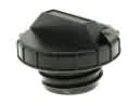 GMC Gas Cap
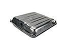 GMC Fuel Tank
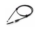 GMC Throttle Cable
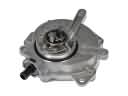 GMC Vacuum Pump
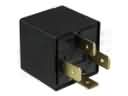 GMC Daytime Running Light Relay
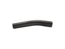 GMC Fuel Filler Hose
 GMC Fuel Injector O-Ring
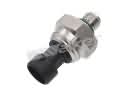 GMC Fuel Pressure Sensor
 GMC Fuel Pump Seal
 GMC Fuel Pump Strainer
 GMC Fuel Tank Strap
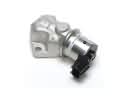 GMC Idle Control Valve
Browse GMC Fuel Rail by Models
Acadia Sierra 1500 Yukon Canyon Sierra 2500 HD Terrain Envoy Sonoma Typhoon Envoy XL Envoy XUV Savana 2500 Savana 3500 Sierra 2500 Sierra 3500 Yukon XL Acadia Limited C2500 C3500 K2500 K3500 Savana 1500 Yukon XL 1500 C2500 Suburban K2500 Suburban Sierra 1500 Classic Sierra 1500 HD Sierra 1500 HD Classic Sierra 1500 Limited Sierra 2500 HD Classic Sierra 3500 Classic Sierra 3500 HD Yukon XL 2500