ChevyParts
My Garage
My Account
Cart
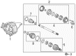
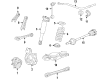
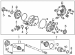
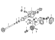
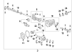
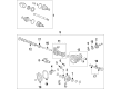
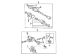
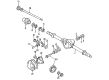
OEM Cadillac Axle Shaft
Car Axle Shaft- Select Vehicle by Model
- Select Vehicle by VIN
Select Vehicle by Model
orMake
Model
Year
Select Vehicle by VIN
For the most accurate results, select vehicle by your VIN (Vehicle Identification Number).
280 Axle Shafts found


Cadillac Axle Assembly, Rear Passenger Side Part Number: 20817952
$878.99 MSRP: $1143.61You Save: $264.62 (24%)Ships in 1-2 Business DaysProduct Specifications- Other Name: Shaft Assembly-Rear Wheel Drive; CV Axle Assembly; Axle Shaft; CV Axle; Shaft, Rear Axle Drive
- Position: Rear Passenger Side
- Replaces: 10394240

Cadillac Axle Assembly, Rear Driver Side Part Number: 84550225
$620.80 MSRP: $981.21You Save: $360.41 (37%)Ships in 1-3 Business DaysProduct Specifications- Other Name: Shaft Assembly-Rear Wheel Drive; Axle; Shaft, Rear Axle Drive
- Position: Rear Driver Side
- Replaces: 23117793, 84127439, 84309445, 84235671


Cadillac Output Shaft, Rear Passenger Side Part Number: 23154589
$199.60 MSRP: $316.89You Save: $117.29 (38%)Ships in 1-2 Business DaysProduct Specifications- Other Name: Shaft-Rear Axle; Axle Shaft; Shaft; Shaft, Rear Axle Drive
- Position: Rear Passenger Side
Cadillac Output Shaft, Rear Driver Side Part Number: 23154590
$161.36 MSRP: $256.18You Save: $94.82 (38%)Ships in 1-2 Business DaysProduct Specifications- Other Name: Shaft-Rear Axle; Axle Shaft; Shaft; Shaft, Rear Axle Drive
- Position: Rear Driver Side

Cadillac Axle Assembly, Rear Passenger Side Part Number: 84550230
$488.39 MSRP: $771.88You Save: $283.49 (37%)Ships in 1-2 Business DaysProduct Specifications- Other Name: Shaft Assembly-Rear Wheel Drive; Axle Shaft; Axle; Shaft, Rear Axle Drive
- Position: Rear Passenger Side
- Replaces: 23117792, 84309450, 84028743

Cadillac Axle Assembly, Rear Passenger Side Part Number: 23401013
$233.59 MSRP: $384.79You Save: $151.20 (40%)Ships in 1-2 Business DaysProduct Specifications- Other Name: Shaft Assembly-Rear Wheel Drive; Axle Shaft; Shaft, Rear Axle Drive
- Position: Rear Passenger Side
- Replaces: 23294658

Cadillac Axle Housing, Rear Part Number: 22968246
$2269.00 MSRP: $2920.20You Save: $651.20 (23%)Ships in 1-3 Business DaysProduct Specifications- Other Name: Axle Assembly-Rear; Axle, Rear Axle
- Position: Rear
Cadillac Axle Housing, Rear Part Number: 22968252
$2269.00 MSRP: $2920.20You Save: $651.20 (23%)Ships in 1-3 Business DaysProduct Specifications- Other Name: Axle Assembly-Rear; Axle, Rear Axle
- Position: Rear
Cadillac Axle Housing, Rear Part Number: 22968251
$2269.00 MSRP: $2920.20You Save: $651.20 (23%)Ships in 1-3 Business DaysProduct Specifications- Other Name: Axle Assembly-Rear; Axle, Rear Axle
- Position: Rear
Cadillac Axle Assembly, Rear Driver Side Part Number: 20817951
$893.96 MSRP: $1155.74You Save: $261.78 (23%)Ships in 1-2 Business DaysProduct Specifications- Other Name: Shaft Assembly-Rear Wheel Drive; CV Axle Assembly; Axle Shaft; CV Axle; Shaft, Rear Axle Drive
- Position: Rear Driver Side
- Replaces: 10394239

Cadillac Axle Assembly, Front Part Number: 84865593
$1675.07 MSRP: $2142.30You Save: $467.23 (22%)Ships in 1-3 Business DaysProduct Specifications- Other Name: Axle Assembly-Front; Differential; Axle Shaft; Differential Assembly; Axle; Axle, Front Axle And Axle Center
- Position: Front
- Replaced by: 85520534
Cadillac Axle Assembly, Front Part Number: 84865594
$1370.25 MSRP: $1750.00You Save: $379.75 (22%)Ships in 1-3 Business DaysProduct Specifications- Other Name: Axle Assembly-Front; Differential; Axle Shaft; Differential Assembly; Axle; Axle, Front Axle And Axle Center
- Position: Front
- Replaces: 84798159, 84798154

Cadillac Differential Assembly, Front Part Number: 87836729
$1324.85 MSRP: $1691.60You Save: $366.75 (22%)Ships in 1-2 Business DaysProduct Specifications- Other Name: Axle Assembly-Front; Carrier; Axle; Axle, Front Axle And Axle Center
- Position: Front
- Replaced by: 85754735

Cadillac Axle Assembly Part Number: 89060311
$58.90 MSRP: $435.21You Save: $376.31 (87%)Ships in 1-2 Business DaysProduct Specifications- Other Name: Shaft Kit, Rear Axle Drive; Axle Shaft
- Position: Rear


Cadillac Differential Assembly, Front Part Number: 23312174
Product Specifications- Other Name: Axle Assembly-Front; Differential
- Position: Front
- Replaces: 20980290, 23484385, 23186399


Cadillac Differential Assembly, Front Part Number: 23312177
$1206.09 MSRP: $1906.26You Save: $700.17 (37%)Product Specifications- Other Name: Axle Assembly-Front; Differential
- Position: Front
- Replaces: 23484389
Cadillac Axle Assembly, Front Part Number: 85524479
$1079.50 MSRP: $1389.31You Save: $309.81 (23%)Product Specifications- Other Name: Axle Assembly-Front; Differential Assembly; Carrier; Axle; Axle, Front Axle And Axle Center
- Position: Front
- Replaces: 84648802, 84829188, 84605752, 84958557

Cadillac Axle Shafts, Rear Part Number: 12380993
Product Specifications- Other Name: Shaft, R/A; Axle Shaft; Shaft, Rear Axle Drive
- Position: Rear

Cadillac Axle Shaft, Front Part Number: 26056795
Product Specifications- Other Name: Shaft, Front Wheel Drive; Shaft
- Position: Front

Cadillac Axle Shaft, Rear Part Number: 26010417
Product Specifications- Other Name: Shaft, Rear Axle Drive; Axle Shafts
- Position: Rear
| Page 1 of 14 |Next >
1-20 of 280 Results
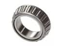
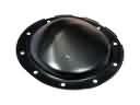
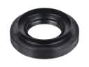
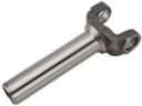
Cadillac Axle Shaft
Want to cut long-term maintenance and repair costs? Choose OEM Axle Shaft. Those parts deliver top durability you can trust. On our site, you'll find a huge catalog of genuine Cadillac parts. Prices are unbeatable, so you can keep more in your pocket. Every OEM Cadillac Axle Shaft includes a manufacturer's warranty. You can also get an easy return policy that keeps buying risk free. Fast delivery, get your car on the road quickly. It's simple to search, compare, and order. Stop guessing about quality or fit. Order today and save with parts that last.
Cadillac Axle Shaft Parts Questions & Experts Answers
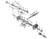
- Q: How to replace the rear axle shaft on Cadillac Escalade?A:The first stage to replace the rear Axle Shaft requires the driver to lift the vehicle before removing tire and wheel components. The procedure starts with releasing the brake caliper mounting bracket along with the rear Wheel Speed Sensor. Perform the sequence of steps which begins with removing the gasket alongside the rear axle housing cover then continue with the pinion shaft locking bolt. Owners must remove the pinion shaft completely from axles without a locking differential but should only partially remove it from locking differential axles before rotating the case until the pinion shaft contacts the housing. The screwdriver serves to turn the c-lock while it approaches the thrust block alignment configuration and afterward push the Axle Shaft flange toward the differential until the c-lock releases from the Axle Shaft's button where the shaft remains untwisted to maintain proper alignment. The j 2619-01 (slide hammer) alongside the j 45859 (remover/installer) should be used for axle shafts which prove difficult to extract. Insert the Axle Shaft into the rear axle housing while it enters the differential side gear splines properly. To install lock type axles set the c-lock onto the button end of the shaft whereas lock type axles should position the pinion shaft partially out with c-lock flat against the thrust block before insertion into the differential gear. Attach the pinion shaft through its hole until it lines up with the differential case bolt hole before installing a new locking pinion bolt that needs a torque of 36 nm (27 lb ft) for 8.6-inch axle installation or 50 nm (37 lb ft) for 9.5 ld-inch axle tightening. After securing the rear Wheel Speed Sensor reattach the brake caliper mounting bracket then the rear axle housing cover together with its gasket. The last step consists of reattaching the tire along with wheel assembly followed by adding proper lubricant to the rear axle and lowering the vehicle.
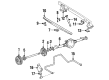
- Q: How to replace the front left axle shaft on Cadillac SRX?A:The replacement of the front left wheel drive shaft begins with vehicle lift and support followed by removal of the left front wheel and tire. Disconnect the left Steering Knuckle Tie Rod End from the Steering Knuckle yet keep the Tie Rod End jam nut tight. The brake rotor requires a drift or punch that should go through it and rest against the brake caliper mounting bracket to stop Wheel Hub and bearing motion. New replacement nuts must be used for replacing the wheel drive shaft Spindle Nut because previous usage invalidates it. The Wheel Speed Sensor electrical connector should be detached from the sensor before moving the wiring harness away from the Ball Joint position. The Ball Joint on the left side upper section should be detached from its connection to the Steering Knuckle. Fix the Wheel Hub remover (J 45859) onto the Wheel Hub but secure it with wheel nuts only after you support the wheel drive shaft until it is fully removed. Disengage the left front wheel drive shaft from the Wheel Hub and bearing through use of the Wheel Hub remover j 45859 until successful removal from the vehicle. The technicians must use slide hammer with adapter (J 2619-O1) combined with extension (J 29794) and Axle Shaft puller (J 45341). They should place the puller (J 45341) into the inner joint pull groove area of the wheel drive shaft. The assembled tools should be used to disengage the wheel drive shaft from the intermediate wheel drive shaft. When keeping the intermediate wheel drive shaft remove the wheel drive shaft retaining ring along with the o-ring from their designated grooves. Attach a new o-ring and wheel drive shaft retaining ring to the intermediate wheel drive shaft following gm p/n 01051344 (Canadian P/N 993037) grease application to the splines. The left front wheel drive shaft will install to the intermediate wheel drive shaft while extracting outward force on the inner joint housing to achieve proper coupling. First install both the left wheel drive shaft to its hub and bearing followed by its Ball Joint installation on the Steering Knuckle before connecting the speed sensor electrical cable. The new wheel drive shaft Spindle Nut should be loosely threaded then a drift or punch should be placed into the rotor against the caliper mounting bracket until the Spindle Nut reaches 160 nm (118 ft. Lbs. Of torque). Before vehicle lowering complete the procedure by connecting the outer Tie Rod End to the Steering Knuckle followed by wheel and tire assembly installation.
- Q: What tools are required to service and repair the axle shaft assembly for front wheel drive shaft replacement (FE7) on Cadillac DeVille?A:For the following requirements of servicing and repair of the Axle Shaft assembly, namely, front Axle Shaft change (FE7), the following tools are required: slide hammer (J 2619-O1), extension (J 29794), Axle Shaft remover (J 33008-A), hub spindle remover (J 42129). Start by lifting and supporting the vehicle, and discard away the tire and the wheel assembly. In case, there is an automatic level control, remove the automatic level sensor link from the ball stud located on the lower Control Arm. Next, pull off the outer Tie Rod End from the Steering Knuckle without turning the Tie Rod End jam nut. Bore a drift or punch into the brake rotor against the brake caliper to keep the Wheel Hub and bearing from turning. It is very important to change the front axle nut to a new one when it has been tampered with. Remove and dispose of the Axle Shaft Spindle Nut that maintains the relationship between the Axle Shaft and the hub, then remove the stabilizer shaft link. After disconnecting electrical connector from sensor repositioned the wheel speed sensor wiring harness far from the Ball Joint. Unplug the electrical connector from the wheel speed sensor and reposition the wiring harness and unplug the lower Ball Joint from the Steering Knuckle. Attach the hub spindle remover (J 42129) to the Wheel Hub and tighten it using wheel nuts, which keep the Axle Shaft until removed completely. Disengage the Axle Shaft from the Wheel Hub and bearing using the hub spindle remover (J 42129) while supporting the Axle Shaft. Combine the slide hammer (J 2619-O1), extension (J 29794), and Axle Shaft remover (J 33008-A) to ensure that the Axle Shaft lifts away from the transaxle and that it is removed from the car. For installation, install Axle Shaft into the transaxle and make sure that it is properly engaged by pulling outward on the inner tripot housing. Mount the Axle Shaft to the hub and bearing, join the Ball Joint to the Steering Knuckle, and the wheel speed sensor electrical connector. Mount the stabilizer shaft link then, get a drift/punch and jam it into the rotor versus the caliper, to keep the hub from rotating on its bearing. Clean and add a small bead of loctite dri-loc 201 (GM P/N 12345493) or equivalent to the entire length of the male thread on the drive axle prior to installation of the new front axle nut and then tighten it to 230 nm (170 ft. Lbs.). Finally connect the outer Tie Rod End to the Steering Knuckle, reconnect the automatic level sensor link if present and install the tire and wheel assembly and lower the vehicle.