ChevyParts
My Garage
My Account
Cart
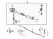
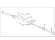
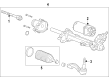
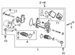
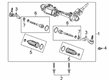
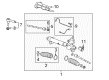
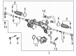
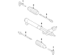
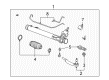
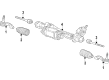
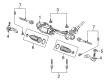
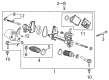
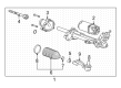
OEM Cadillac Rack And Pinion
Steering Rack And Pinion- Select Vehicle by Model
- Select Vehicle by VIN
Select Vehicle by Model
orMake
Model
Year
Select Vehicle by VIN
For the most accurate results, select vehicle by your VIN (Vehicle Identification Number).
139 Rack And Pinions found

Cadillac Steering Gear Part Number: 26070311
$426.15 MSRP: $670.53You Save: $244.38 (37%)Ships in 1-3 Business DaysProduct Specifications- Other Name: Gear, Steering; Gear Assembly

Cadillac Steering Gear Part Number: 25983243
$518.65 MSRP: $819.74You Save: $301.09 (37%)Ships in 1-3 Business DaysProduct Specifications- Other Name: Gear Assembly-Steering; Gear Assembly; Gear, Steering
- Replaces: 10368440, 15257558, 25848038, 25765135, 25820358


Cadillac Gear Assembly Part Number: 15173571
$420.33 MSRP: $661.37You Save: $241.04 (37%)Ships in 1-3 Business DaysProduct Specifications- Other Name: Gear, Steering
- Replaces: 15076532

Cadillac Gear Assembly Part Number: 87820242
$875.30 MSRP: $1154.66You Save: $279.36 (25%)Ships in 1-2 Business DaysProduct Specifications- Other Name: Gear Assembly-Electrical Belt Drive Rack & Pinion Steering; Rack; Gear, Steering
- Replaced by: 85039777

Cadillac Rack Part Number: 85124589
$1065.62 MSRP: $1367.40You Save: $301.78 (23%)Ships in 1-3 Business DaysProduct Specifications- Other Name: Gear Assembly-Electrical Belt Drive Rack & Pinion Steering; Gear, Steering

Cadillac Gear Assembly Part Number: 85140551
$1283.37 MSRP: $1647.64You Save: $364.27 (23%)Ships in 1-3 Business DaysProduct Specifications- Other Name: Gear Assembly-Electrical Belt Drive Rack & Pinion Steering; Rack; Gear, Steering
- Replaced by: 85735179

Cadillac Gear Assembly Part Number: 84706248
$1905.68 MSRP: $2448.56You Save: $542.88 (23%)Ships in 1-3 Business DaysProduct Specifications- Other Name: Gear Assembly-Electrical Belt Drive Rack & Pinion Steering; Rack; Gear, Steering
- Replaces: 84487238, 84253039, 84320490

Cadillac Steering Gear Part Number: 19431727
$709.56 MSRP: $913.20You Save: $203.64 (23%)Ships in 1-2 Business DaysProduct Specifications- Other Name: Gear Assembly, Steering; Gear Assembly; Gear, Steering
- Replaces: 15950145
Cadillac Rack Part Number: 86804805
$864.51 MSRP: $1108.57You Save: $244.06 (23%)Ships in 1-3 Business DaysProduct Specifications- Other Name: Gear Assembly-Electrical Belt Drive Rack & Pinion Steering; Gear, Steering
- Replaced by: 85024633

Cadillac Steering Gear Part Number: 85113640
$1092.68 MSRP: $1402.23You Save: $309.55 (23%)Product Specifications- Other Name: Gear Assembly-Electrical Belt Drive Rack & Pinion Steering; Gear Assembly; Rack; Gear, Steering
- Replaced by: 85776993

Cadillac Steering Gear Part Number: 25911321
$1187.42 MSRP: $1528.21You Save: $340.79 (23%)Ships in 1-3 Business DaysProduct Specifications- Other Name: Gear Assembly-Steering

Cadillac Steering Gear Part Number: 19419353
$1254.17 MSRP: $1614.11You Save: $359.94 (23%)Ships in 1-2 Business DaysProduct Specifications- Other Name: Gear Assembly, Steering; Gear Assembly; Gear, Steering
- Replaces: 22777702, 25930832, 20962760, 25980224

Cadillac Steering Gear Part Number: 84940449
$1505.46 MSRP: $1933.48You Save: $428.02 (23%)Ships in 1-3 Business DaysProduct Specifications- Other Name: Gear Assembly-Electrical Belt Drive Rack & Pinion Steering; Gear, Steering
- Replaced by: 86815641

Cadillac Steering Gear Part Number: 84952336
$1718.10 MSRP: $2207.15You Save: $489.05 (23%)Ships in 1-3 Business DaysProduct Specifications- Other Name: Gear Assembly-Electrical Belt Drive Rack & Pinion Steering; Gear Assembly; Rack; Gear, Steering
- Replaces: 23457123, 84591549, 84160636

Cadillac Steering Gear Part Number: 85520323
$985.82 MSRP: $1268.76You Save: $282.94 (23%)Ships in 1-3 Business DaysProduct Specifications- Other Name: Gear Assembly-Electrical Belt Drive Rack & Pinion Steering; Gear Assembly; Gear, Steering
- Replaced by: 87853955
Cadillac Steering Gear Part Number: 84952341
$2139.33 MSRP: $2749.28You Save: $609.95 (23%)Ships in 1-3 Business DaysProduct Specifications- Other Name: Gear Assembly-Electrical Belt Drive Rack & Pinion Steering; Gear Assembly; Gear, Steering
- Replaces: 23209963, 23456579, 84228072, 23142351, 84591543, 84297139
Cadillac Gear Assembly Part Number: 84815774
$908.40 MSRP: $1165.07You Save: $256.67 (23%)Ships in 1-3 Business DaysProduct Specifications- Other Name: Gear Assembly-Electrical Belt Drive Rack & Pinion Steering; Rack; Gear, Steering
Cadillac Gear Assembly Part Number: 85124591
$1092.68 MSRP: $1402.22You Save: $309.54 (23%)Ships in 1-3 Business DaysProduct Specifications- Other Name: Gear Assembly-Electrical Belt Drive Rack & Pinion Steering; Rack
- Replaced by: 85024634
Cadillac Gear Assembly Part Number: 84706249
$2052.94 MSRP: $2638.08You Save: $585.14 (23%)Product Specifications- Other Name: Gear Assembly-Electrical Belt Drive Rack & Pinion Steering; Rack; Gear, Steering
- Replaces: 84384654, 84487242
Cadillac Steering Gear Part Number: 15173572
$400.90 MSRP: $630.79You Save: $229.89 (37%)Product Specifications- Other Name: Gear, Steering; Gear Assembly
- Replaces: 15077365
| Page 1 of 7 |Next >
1-20 of 139 Results
Cadillac Rack And Pinion
Choose OEM Rack And Pinion, you're making the optimal decision for superior quality and perfect performance. You can feel confident because each component goes through stringent quality checks. Every part is carefully built to comply with Cadillac's factory specifications. You'll enjoy a smooth, worry-free installation that fits just right. At ChevyPartsGiant.com, you'll find it easy to get top-quality OEM Cadillac Rack And Pinion. You can shop at highly competitive prices and protect your budget. All our genuine Cadillac parts include a dependable manufacturer's warranty. You'll also appreciate our straightforward return policy and swift delivery services for extra convenience.
Cadillac Rack And Pinion Parts and Q&A
- Q: How to replace the Rack and Pinion on left-hand drive on Cadillac CTS?A:To replace the Rack And Pinion on the left hookers upper body vehicles, start by installing the engine support fixture. Remove the front air deflector and the front compartment lower noise shield, and locate drain pans underneath the vehicle as necessary. Remove the lower intermediate Steering Shaft from the Rack And Pinion and can remove steering linkage outer tie rods on the steering knuckles and lower control arms on the steering knuckles. Take out the power steering Rack And Pinion inlet pipe bracket bolt and all fasteners that hook the power steering Rack And Pinion inlet and outlet hose to the frame, then remove the hoses from the Rack And Pinion. Jack up the front frame using jackstands then remove the left and right side engine mount bolts; unplug the electrical harnesses that are connected to the front frame, and disconnect power steering Rack And Pinion solenoid electrical connector. Take off the front frame bolts and carefully raise the vehicle on the hoist to give enough room for the removal of the Rack And Pinion. Take out the nuts that secure the Rack And Pinion to the frame at the front and then remove the Rack And Pinion from the front frame. For install the Rack And Pinion to the frame front, install the Rack And Pinion bolts and tighten them to 60 nm plus 80 degrees (44 lb ft). Lower the vehicle, while front frame must be aligned with the engine mounts and then begin the engine mount bolts hand. Mount the front frame bolts and pull the engine mount bolts. Reconnect the power steering solenoid electric connector and any electrical harnesses back to the front frame. Take off the jack stands, attach the power steering Rack And Pinion inlet and outlet hoses to the Rack And Pinion while hooking up the power steering Rack And Pinion inlet pipe bracket bolt, which bolts to 22.5 nm (17 lb ft). Reattach any fasteners for the power steering hoses, reattach the lower Control Arm to steering knuckles, and reconnect steering linkage outer tie rods. Connect the lower intermediate Steering Shaft to the Rack And Pinion, clean the excess, and reinstall the front compartment lower noise shield as well as the front air deflector. Finally, pull out the engine support fixture, add to and bleed the power steering system, and toe front.
- Q: How to safely and effectively replace the Rack and Pinion steering gear on Cadillac Escalade?A:Rack And Pinion replacement starts with conducting the high voltage disabling procedure before testing for high voltage presence because neglecting this safety protocol can lead to fatal injuries. Place the vehicle's wheels directly ahead then lock down the Steering Wheel with an anti-rotation pin or Steering Column lock or secure strap to safeguard the sir system from damage. Avoid un-centering the sir coil assembly by maintaining both the Steering Wheel stationary and the front tires motionless during the disconnection of the Steering Column and intermediate shaft(s) and Rack And Pinion. The damaged Rack And Pinion harness needs replacement while protective covering must stay in place on the wiring harness until a proper position is achieved. Criminal operations should start with the tire and wheel assembly detachment followed by steaming out the steering shaft coupling bolt so the coupling can be separated from the Rack And Pinion. Disassemble the steering linkage outer tie rods by removing their outer tie rod nuts then discard these nuts before separating the tie rods from the steering knuckles. After installing jackstands under the Rack And Pinion remove both Rack And Pinion bolts and carefully extract the Rack And Pinion from the vehicle. Install the new Rack And Pinion onto its support fixture with jackstands while hand-tightening all bolts initially. Finish by adjusting right side bolts to 100 nm torque (74 lb ft) and left side bolts to 200 nm torque (148 lb ft). During installation connect the steering linkage outer tie rods to their positions on the steering knuckles and torque the new outer tie rod nuts to 60 nm (44 lb ft). The steering coupling needs installation between Rack And Pinion components while tightening the coupling bolt to 47 nm (35 lb ft) torque then reinstalling the front tire and wheel assemblies. Finish the power steering control module setup after running the high voltage enabling procedure.


Related Cadillac Parts
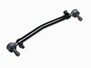 Cadillac Drag Link
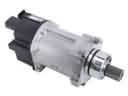 Cadillac Power Steering Assist Motor
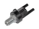 Cadillac Power Steering Control Valve
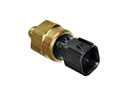 Cadillac Power Steering Pressure Switch
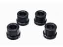 Cadillac Rack & Pinion Bushing
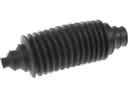 Cadillac Rack and Pinion Boot
 Cadillac Radius Heat Shield
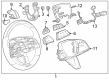
 Cadillac Steering Column Cover
 Cadillac Steering Gearbox
 Cadillac Tie Rod
 Cadillac Tie Rod Adjusting Sleeve
 Cadillac Upper Steering Column Bearing