
Popular OEM Chevrolet Tahoe Parts
- Body & Hardware Parts View More >
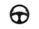
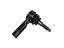
- Steering Parts View More >
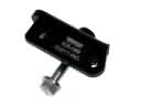
- Electrical Parts View More >
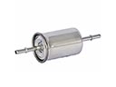
- Air & Fuel Delivery Parts View More >
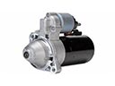
- Charging & Starting Parts View More >
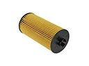
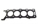
- Engine Parts View More >
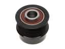
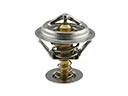
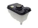
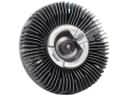
- Belts & Cooling Parts View More >
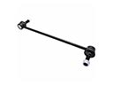
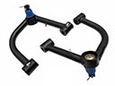
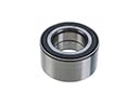
- Suspension Parts View More >
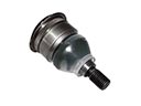
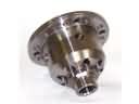
- Driveline & Axles Parts View More >
- Emission Control & Exhaust Parts View More >
- Transmission Parts View More >
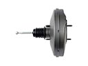
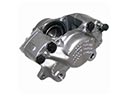
- Brakes Parts View More >

Why Buy Genuine Chevrolet Tahoe Parts From ChevyPartsGiant.com
Looking for real Chevrolet Tahoe parts? ChevyPartsGiant.com may be a better choice to find genuine parts at wallet-friendly prices. We sell only OEM Chevrolet Tahoe parts, ensuring perfect fit, reliability, and long-term performance. With our website, you can easily get access to the same parts found at local Chevrolet stores. All components are produced by Chevrolet and are exclusively fitted on Chevrolet Tahoe automobiles. By shopping at our store, you can enjoy the quality of the Chevrolet factory without the high prices of brick-and-mortar facilities. We achieve this because we are an online store operating at lower costs, which we pass on to you. We also have a user-friendly platform where you can find and order genuine Chevrolet Tahoe parts swiftly. We are here to make your process of restoring a Chevrolet Tahoe or dealing with simple repairs quick and inexpensive. We also make it easy to obtain Chevrolet Tahoe parts at competitive shipping prices and a team of knowledgeable staff ready to take your order. Choose ChevyPartsGiant.com to save time and money, as well as keep your Chevrolet Tahoe in the good condition.
Since 1994 Chevrolet has manufactured the Tahoe full-size SUV through five generations which demonstrates powerful V8 engine profiles along with advanced transmissions. The Chevrolet Tahoe advanced on by providing its customers with four unique powertrain solutions, that started as low as the 4.8L up to the top point on the 6.2L V8 engine, and fifth generation held 3.0L Duramax I6 turbo diesel powered by 277 horsepower along with the 460 lb-ft of torque. The 4th generation of Chevrolet Tahoe includes the Ecotec3 V8 engines that expect a 355hp combined with 383 lb-ft of torque on the 5.3L and a 420hp and 460 lb-ft available on its 6.2L variant. Chevrolet Tahoe transmits the technology has changed from primitive 4-speed automatics to sophisticated 10-speed Hydra-Matic automatics. A 6-speed automatic was standard in earlier fourth-generation models, with the 10-speed becoming available later in higher trims. A 6-speed 6L80 automatic transmission system was introduced during the third generation to boost both efficiency and driving performance. The current Chevrolet Tahoe comes with measurements of 210.7 inches in length and 81.1 inches in width although it weighs above 5,473 pounds as a whole. The Police Pursuit Vehicle (PPV) alongside Special Service Vehicle (SSV) both developed from Chevrolet Tahoe exist as major law enforcement and government agency vehicles. Genuine parts dedicated to Chevrolet Tahoe vehicle maintenance can be acquired which provides both superior quality components and factory-preferred fitment for extended vehicle lifespan and optimal performance.
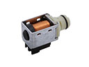
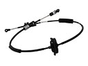
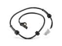
Chevrolet Tahoe presents three concerns grouped by HVAC control, brake sensing, and door hardware. These affect comfort, safety, and daily usability. In the climate system, a failed AC mode door actuator causes wrong temperature or incorrect air outlet selection. Miscalibration or broken gears can add clicking and poor travel. Diagnosis on the Chevrolet Tahoe includes scanning the HVAC module for codes and running actuator recalibration. If airflow or temperature stay incorrect, replace the actuator and verify linkage engagement on the Tahoe. For braking, a faulty front wheel speed sensor triggers the ABS light and creates unwanted low speed pulsing. Inspect hub wiring for damage, check sensor air gap, and replace the wheel speed sensor when readings drop. Clear codes, confirm stable wheel speed data, and road test the Tahoe on varied surfaces. For body hardware, a cracked inside or outside door handle causes latch release failure and inconsistent opening effort. Service on the Chevrolet Tahoe includes replacing the damaged door handle, checking latch alignment, and lubricating pivots and cables. These steps restore function and help the Chevrolet Tahoe stop reliably, stay comfortable, and operate securely every day.
Chevrolet Tahoe Parts and Q&A
- Q: How to service and repair the alternator on Chevrolet Tahoe?A:To service and repair the alternator, firstly, unconnection of the negative battery cable and removal of the accessory drive belt. The second step is to disconnect the electrical connections and eliminate the generator. To install, screw the generator in, reconnect the electrical connection, replace the accessory drive belt and reconnect the negative battery cable.
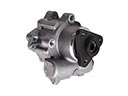
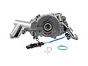
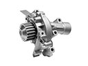
- Q: How to replace a water pump on Chevrolet Tahoe?A:In order to change water pump, empty the water pump, remove the air inlet duct, drain the coolant, and remove hoses. Removal of the fan shroud, cooling fan and drive belt. Install the new water pump and hoses, reconnect the parts and charge the cooling system. Do not take seal tabs to avert flow of the coolant.
- Q: How to replace the camshaft on Chevrolet Tahoe?A:The camshaft will need to be removed to change the radiator support, valve lifters, and engine front cover. Bolt it with the J 42386-A device. Position the marks of the camshaft and crankshaft, then take off CMP actuator and timing chain. Fit the new camshaft and lubricate and align. Install parts and make sure they are aligned and finally tightened.


