ChevyParts
My Garage
My Account
Cart
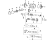
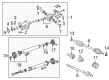
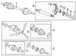
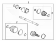
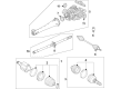
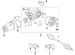
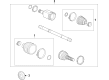
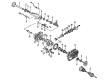
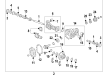
OEM Chevrolet CV Boot
Axle Boot- Select Vehicle by Model
- Select Vehicle by VIN
Select Vehicle by Model
orMake
Model
Year
Select Vehicle by VIN
For the most accurate results, select vehicle by your VIN (Vehicle Identification Number).
215 CV Boots found


Chevrolet Inner Boot, Rear Part Number: 19301960
$76.35 MSRP: $125.77You Save: $49.42 (40%)Product Specifications- Other Name: Boot Kit, Rear Axle Universal Joint; CV Boot
- Position: Rear

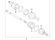
Chevrolet Inner Boot, Front Part Number: 42697380
$27.75 MSRP: $49.57You Save: $21.82 (45%)Ships in 1-3 Business DaysProduct Specifications- Other Name: Boot Kit-Front Wheel Drive Shaft CV Joint Inner; CV Boot; Boot Kit, Front Wheel Drive Axle Shaft
- Position: Front Inner
- Replaces: 95394775

Chevrolet Boots Part Number: 26013237
$59.76 MSRP: $106.72You Save: $46.96 (44%)Ships in 1-3 Business DaysProduct Specifications- Other Name: Seal Kit; CV Boot
- Replaced by: 26026241

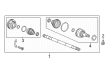
Chevrolet Inner Boot Part Number: 95908489
$43.62 MSRP: $68.32You Save: $24.70 (37%)Ships in 1-3 Business DaysProduct Specifications- Other Name: Boot Kit-Front Wheel Drive Shaft CV Joint Inner; CV Boot; Boot Kit, Front Wheel Drive Axle Shaft
- Position: Front

Chevrolet Outer Boot Part Number: 92290839
$40.45 MSRP: $66.20You Save: $25.75 (39%)Product Specifications- Other Name: Boot Kit, Rear Axle Universal Joint; CV Boot
- Position: Rear Outer
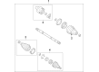
Chevrolet Inner Boot, Front Part Number: 42697379
$18.42 MSRP: $28.86You Save: $10.44 (37%)Ships in 1-3 Business DaysProduct Specifications- Other Name: Boot Kit-Front Wheel Drive Shaft CV Joint Inner; CV Boot; Boot Kit, Front Wheel Drive Axle Shaft
- Position: Front Inner
- Replaces: 95394774

Chevrolet Outer Boot, Front Part Number: 42527030
$45.36 MSRP: $74.69You Save: $29.33 (40%)Ships in 1-3 Business DaysProduct Specifications- Other Name: Boot Kit, Front Wheel Drive Axle Shaft; CV Boot
- Position: Front
- Replaces: 95228794

Chevrolet Outer Boot Part Number: 95908468
$71.84 MSRP: $118.35You Save: $46.51 (40%)Ships in 1-2 Business DaysProduct Specifications- Other Name: Boot Kit, Front Wheel Drive Axle Shaft; CV Boot; Boots
- Position: Front Outer

Chevrolet Boot Kit Part Number: 42721984
$40.32 MSRP: $63.15You Save: $22.83 (37%)Ships in 1-3 Business DaysProduct Specifications- Other Name: Boot Kit-Front Wheel Drive Shaft Tri-Pot & CV Joint; CV Boot; Boot Kit, Front Wheel Drive Axle Shaft
- Position: Front
Chevrolet Outer CV Joint Boot, Rear Part Number: 84207690
$14.77 MSRP: $36.04You Save: $21.27 (60%)Ships in 1-2 Business DaysProduct Specifications- Other Name: Boot Kit-Rear Wheel Drive Shaft CV Joint; CV Boot; Outer Boot
- Position: Rear

Chevrolet Inner CV Joint Boot, Front Part Number: 84148576
$37.61 MSRP: $58.91You Save: $21.30 (37%)Ships in 1-3 Business DaysProduct Specifications- Other Name: Boot Kit, Front Wheel Drive Axle Shaft; CV Boot; Inner Boot
- Position: Front

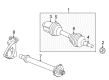
Chevrolet Inner Joint Assembly, Rear Driver Side Part Number: 84138225
$48.74 MSRP: $76.35You Save: $27.61 (37%)Ships in 1-3 Business DaysProduct Specifications- Other Name: Boot Kit-Rear Wheel Drive Shaft CV Joint; Boot Kit, Rear Axle Universal Joint
- Position: Rear Driver Side

Chevrolet Outer Boot, Front Part Number: 22674175
$39.76 MSRP: $65.50You Save: $25.74 (40%)Ships in 1-2 Business DaysProduct Specifications- Other Name: Boot Kit, Front Axle; CV Boot; Boot Kit, Front Wheel Drive Axle Shaft
- Position: Front

Chevrolet Outer CV Joint Boot, Front Part Number: 84227478
$29.29 MSRP: $48.24You Save: $18.95 (40%)Ships in 1-2 Business DaysProduct Specifications- Other Name: Boot Kit, Front Wheel Drive Axle Shaft
- Position: Front

Chevrolet Outer Boot, Rear Part Number: 19149882
$20.56 MSRP: $32.21You Save: $11.65 (37%)Ships in 1-3 Business DaysProduct Specifications- Other Name: Boot Kit, Rear Axle Universal Joint; CV Boot; Inner Boot
- Position: Rear
Chevrolet Inner CV Joint Boot, Rear Part Number: 84387108
$30.80 MSRP: $48.24You Save: $17.44 (37%)Ships in 1-3 Business DaysProduct Specifications- Other Name: Boot Kit-Rear Wheel Drive Shaft Tri-Pot Joint; CV Boot; Inner Boot; Boot Kit, Rear Axle Universal Joint
- Position: Rear
- Replaces: 84207708

Chevrolet Boot Kit Part Number: 42756982
$39.42 MSRP: $64.93You Save: $25.51 (40%)Ships in 1-3 Business DaysProduct Specifications- Other Name: Boot Kit-Front Wheel Drive Shaft Tri-Pot & CV Joint; CV Boot; Boot Kit, Front Wheel Drive Axle Shaft
- Position: Front
- Replaces: 42721962
Chevrolet Outer Boot Part Number: 95228723
$56.96 MSRP: $90.45You Save: $33.49 (38%)Ships in 1-2 Business DaysProduct Specifications- Other Name: Boot Kit, Front Wheel Drive Axle Shaft; CV Boot
- Position: Front Outer


Chevrolet Inner Boot, Front Part Number: 26062615
$27.79 MSRP: $43.53You Save: $15.74 (37%)Product Specifications- Other Name: Boot Kit, Front Wheel Drive Axle Shaft; CV Boot; Boot Kit, Front Axle
- Position: Front

Chevrolet Boot Kit, Front Part Number: 84392104
$27.14 MSRP: $42.51You Save: $15.37 (37%)Product Specifications- Other Name: Boot Kit, Front Wheel Drive Axle Shaft; CV Boot; Outer Boot
- Position: Front
- Replaced by: 87842370
| Page 1 of 11 |Next >
1-20 of 215 Results
Chevrolet CV Boot
Want to cut long-term maintenance and repair costs? Choose OEM CV Boot. Those parts deliver top durability you can trust. On our site, you'll find a huge catalog of genuine Chevrolet parts. Prices are unbeatable, so you can keep more in your pocket. Every OEM Chevrolet CV Boot includes a manufacturer's warranty. You can also get an easy return policy that keeps buying risk free. Fast delivery, get your car on the road quickly. It's simple to search, compare, and order. Stop guessing about quality or fit. Order today and save with parts that last.
Chevrolet CV Boot Parts Questions & Experts Answers
- Q: How to replace the outer CV boot on the wheel drive shaft on Chevrolet Colorado?A:The replacement of the outer wheel drive shaft outer joint together with boot requires these essential tools: the replacement requires drive axle seal clamp plier j 35910 alongside snap ring pliers j 8059. Drive axle seal clamp plier (J 35910) and snap ring pliers (J 8059). First remove the inner seal before you cut the large retaining clamp at the c/v joint using a hand grinder. After cutting discard this clamp. Cut through and eliminate the small retaining clamp on the outer seal's little end. Keep the c/v joint connected to the driveshaft bar since removing it would require a new complete driveshaft replacement. Replace the outer c/v joint seal with new grease then dry the c/v joint completely before packing it with cleaning debris. Begin by filling the c/v joint assembly with pre-packaged grease from the kit followed by installation of the new small retaining clamp then new large retaining clamp onto the outer seal. Place the small end of the outer seal into the c/v joint outer seal groove of the driveshaft bar using only the proper fasteners at their assigned locations. Gather a torque wrench and breaker bar with the drive axle seal clamp plier (J 35910) to tighten the small retaining clamp to the outer seal at 136 nm (100 lb ft). Guide the large exterior part of the seal onto the c/v joint before placing the lip into its groove and smooth out air bubbles through outer seal manipulation. User must install the large retaining clamp to the c/v joint housing by using the drive axle seal clamp plier (J 35910) together with a breaker bar and torque wrench to achieve 176 nm (130 lb ft) torque. Users must then check the clamp ear gap dimension before angulating the c/v joint multiple times to spread the grease and finally installing the inner seal.
- Q: What tools are required for servicing and repairing the CV Boot and CV Joint, and what are the steps involved on Chevrolet Malibu?A:To service and repair the constant velocity joint boot, for the wheel drive shaft inner joint and boot replacement, the following tools are used. It includes: snap ring pliers (J 8059), drive axle seal clamp pliers (J 35910). Start by making certain that you do not sever inboard boot of wheel drive shaft, since this could damage sealing surface and cause vehicle wear-in to occur quickly. If there is present a small swage ring, then use a hand grinder to remove it, cutting it carefully, without damaging the halfshaft bar; otherwise strip off small seal retaining clamp using side cutters and throw it away. Next, pull out the big seal retaining clamp from the tripot joint off by using side cutters and throwing it away. Remove the inboard seal from the trilobal tripot bushing at the large diameter and push seal off the join from the half shaft bar. Take off the housing from the tripot joint spider and the halfshaft bar. Remove the spacer ring using snap ring pliers (J 8059) and spread the spider assembly as well as the tripot boot, discarding the boot and rings. Clean the halfshaft bar with use of the wire brush to eliminate the rust in boot mounting region and establish a damage of needle rollers, needle bearing and examining trunnion for damages if any before putting on the acceptable kit for a damaged range. Mount the halfshaft into a vise with a towel for protection. After washing its hands with water and soap, the patient should place the new small eared clamp onto the small end of the joint seal and slide it both onto the halfshaft bar; the small end of the joint seal now lies in the groove. Crimp the clamp eared with the use of drive axle seal clamp pliers (J 35910), torque wrench, and breaker bar. After being equipped, push the spacer ring in the groove at the halfshaft bar using snap ring pliers (J 8059), and slide the tripot joint spider assembly onto the halfshaft bar (E). Add grease from the service kit to the halfshaft inboard seal and repack the housing making sure the trilobal tripot bushing is flush with the face of the housing. Put in the trilobal tripot bushing into the housing and mount the larger new seal retaining clamp toward the inboard part on the halfshaft. Push the housing onto the tripot joint spider arrangement and align the lip of the seal with the groove. Place the joint assembly at a correct vehicle dimension of 106 mm (4.00 in) and make use of a thin flat blunt tool to even out force from the large seal opening for the trilobal tripot bushing. Register the inboard halfshaft o-ring, tripot structure, and big seal hold down clamp; crimp the clamp with drive axle seal clamp pliers (J 35910) and tighten to 176 n.m (130 lb ft), using the breaker bar and torque wrench if needed. Examine the gap dimension in clamp ear and tighten up until it is 2.6 mm (0.102 in) bigger if greater. Lastly, fully stroke the joint multiple times to spread out the grease.


Related Chevrolet Parts
 Chevrolet 4WD Actuator
 Chevrolet Spindle
 Chevrolet Coil Springs
 Chevrolet Leaf Spring
 Chevrolet Steering Knuckle
 Chevrolet Axle Beam Mount
 Chevrolet Axle Pivot Bushing
 Chevrolet Axle Shaft Retainer
 Chevrolet Axle Support Bushings
 Chevrolet Control Arm Bolt
 Chevrolet Leaf Spring Shackle
 Chevrolet Sway Bar Bracket
Browse Chevrolet CV Boot by Models
Nova S10 Colorado Tahoe Cruze Malibu Camaro Equinox Impala SS Avalanche Silverado 1500 Silverado 2500 HD Caprice Classic Cobalt Suburban Traverse Blazer HHR Sonic Tracker Volt Spark Trax Trailblazer Astro Cavalier Corvette Aveo Beretta C1500 C2500 C3500 Celebrity City Express Corsica Express 1500 Express 2500 Express 3500 K1500 K2500 K3500 Lumina Metro Monte Carlo Prizm S10 Blazer Silverado 2500 Sprint Uplander Venture Lumina APV Silverado 3500 Suburban 1500 Trailblazer EXT Avalanche 1500 Avalanche 2500 Aveo5 C1500 Suburban C2500 Suburban Captiva Sport Citation II Cruze Limited Impala Limited K1500 Suburban K2500 Suburban Malibu Limited Silverado 1500 Classic Silverado 1500 HD Silverado 1500 HD Classic Silverado 2500 HD Classic Silverado 3500 Classic Silverado 3500 HD Spark EV Spectrum Suburban 2500 Suburban 3500 HD