ChevyParts
My Garage
My Account
Cart
OEM Chevrolet Torsion Bar
Suspension Torsion Bar- Select Vehicle by Model
- Select Vehicle by VIN
Select Vehicle by Model
orMake
Model
Year
Select Vehicle by VIN
For the most accurate results, select vehicle by your VIN (Vehicle Identification Number).
65 Torsion Bars found


Chevrolet Torsion Bar, Front Driver Side Part Number: 19330060
$312.71 MSRP: $492.03You Save: $179.32 (37%)Product Specifications- Other Name: Bar, Front Torsion; Ball Joint; Lower Ball Joint; Bar, Front Chassis
- Position: Front Driver Side
- Replaces: 15528965


Chevrolet Torsion Bar, Front Part Number: 15048312
$257.64 MSRP: $405.40You Save: $147.76 (37%)Ships in 1-3 Business DaysProduct Specifications- Other Name: Bar, Front Torsion
- Position: Front
- Replaced by: 19332932

Chevrolet Torsion Bar, Front Driver Side Part Number: 84745477
$258.71 MSRP: $448.59You Save: $189.88 (43%)Product Specifications- Other Name: Bar-Front Torsion; Bar, Front Chassis
- Position: Front Driver Side
Chevrolet Torsion Bar, Front Passenger Side Part Number: 84745479
$262.36 MSRP: $454.90You Save: $192.54 (43%)Ships in 1-3 Business DaysProduct Specifications- Other Name: Bar-Front Torsion; Bar, Front Chassis
- Position: Front Passenger Side


Chevrolet Torsion Bar, Front Driver Side Part Number: 84301245
$259.43 MSRP: $408.22You Save: $148.79 (37%)Product Specifications- Other Name: Bar-Front Torsion; Bar, Front Chassis
- Position: Front Driver Side
- Replaces: 20883356, 23377385

Chevrolet Torsion Bar, Front Driver Side Part Number: 84301251
$298.62 MSRP: $469.84You Save: $171.22 (37%)Ships in 1-3 Business DaysProduct Specifications- Other Name: Bar-Front Torsion; Bar, Front Chassis
- Position: Front Driver Side
- Replaces: 20883362, 23377391
Chevrolet Torsion Bar, Front Driver Side Part Number: 84745485
$295.06 MSRP: $511.61You Save: $216.55 (43%)Ships in 1-3 Business DaysProduct Specifications- Other Name: Bar-Front Torsion; Bar, Front Chassis
- Position: Front Driver Side
Chevrolet Torsion Bar, Front Passenger Side Part Number: 84745483
$269.89 MSRP: $467.95You Save: $198.06 (43%)Ships in 1-3 Business DaysProduct Specifications- Other Name: Bar-Front Torsion; Bar, Front Chassis
- Position: Front Passenger Side
Chevrolet Torsion Bar, Front Driver Side Part Number: 84745481
$266.15 MSRP: $461.49You Save: $195.34 (43%)Ships in 1-3 Business DaysProduct Specifications- Other Name: Bar-Front Torsion; Bar, Front Chassis
- Position: Front Driver Side

Chevrolet Torsion Bar, Front Driver Side Part Number: 15990699
$110.21 MSRP: $164.00You Save: $53.79 (33%)Ships in 1-3 Business DaysProduct Specifications- Other Name: Bar-Front Torsion (Left-Hand)
- Position: Front Driver Side
Chevrolet Torsion Bar, Front Passenger Side Part Number: 15990700
$110.21 MSRP: $164.00You Save: $53.79 (33%)Ships in 1-3 Business DaysProduct Specifications- Other Name: Bar-Front Torsion (Right-Hand)
- Position: Front Passenger Side


Chevrolet Torsion Bar, Front Driver Side Part Number: 15945637
Product Specifications- Other Name: Bar-Front Torsion
- Position: Front Driver Side
Chevrolet Torsion Bar, Front Driver Side Part Number: 84301249
$244.12 MSRP: $384.11You Save: $139.99 (37%)Product Specifications- Other Name: Bar-Front Torsion; Bar, Front Chassis
- Position: Front Driver Side
- Replaces: 23377389, 20883360
Chevrolet Torsion Bar, Front Passenger Side Part Number: 15100047
Product Specifications- Other Name: Bar-Front Torsion; Bar, Front Chassis
- Position: Front Passenger Side
Chevrolet Torsion Bar, Front Driver Side Part Number: 19332967
$67.40 MSRP: $105.58You Save: $38.18 (37%)Product Specifications- Other Name: Bar, Front Torsion; Bar, Front Chassis
- Position: Front Driver Side
- Replaces: 15173584, 20784588
Chevrolet Torsion Bar, Front Passenger Side Part Number: 20784589
Product Specifications- Other Name: Bar-Front Torsion
- Position: Front Passenger Side
- Replaces: 15173585
Chevrolet Torsion Bar, Front Passenger Side Part Number: 20784593
Product Specifications- Other Name: Bar-Front Torsion
- Position: Front Passenger Side
- Replaces: 15945640

Chevrolet Torsion Bar, Front Passenger Side Part Number: 14056382
Product Specifications- Other Name: Bar-Front Torsion; Bar, Front Chassis
- Position: Front Passenger Side
Chevrolet Torsion Bar, Front Driver Side Part Number: 14056381
Product Specifications- Other Name: Bar-Front Torsion; Bar, Front(Coil Type); Bar, Front Chassis
- Position: Front Driver Side
Chevrolet Torsion Bar, Front Passenger Side Part Number: 15990702
Product Specifications- Other Name: Bar, Front Torsion; Bar, Front Chassis
- Position: Front Passenger Side
| Page 1 of 4 |Next >
1-20 of 65 Results
Chevrolet Torsion Bar
Want to cut long-term maintenance and repair costs? Choose OEM Torsion Bar. Those parts deliver top durability you can trust. On our site, you'll find a huge catalog of genuine Chevrolet parts. Prices are unbeatable, so you can keep more in your pocket. Every OEM Chevrolet Torsion Bar includes a manufacturer's warranty. You can also get an easy return policy that keeps buying risk free. Fast delivery, get your car on the road quickly. It's simple to search, compare, and order. Stop guessing about quality or fit. Order today and save with parts that last.
Chevrolet Torsion Bar Parts Questions & Experts Answers
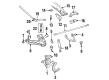
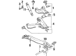
- Q: How to replace the torsion bar anchor in the front suspension on Chevrolet Colorado?A:You need to start by taking out the Torsion Bar in order to replace the anchor in the front suspension. Take off the nuts and bolts from the lower Control Arm, and then take off the Torsion Bar anchor. At installation, the Torsion Bar anchor should be installed first, and fasteners must be used carefully so the car is not harmed. Attach the nuts and bolts to the lower Control Arm tightening them to 80 nm (59 lb ft), and after that, put the Torsion Bar back in.
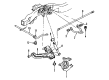
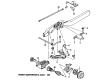
- Q: How to replace the torsion bar and support assembly on Chevrolet Express 3500?A:To remove the Torsion Bar & support assembly, we start by raising & supporting the vehicle. Mount Torsion Bar unloading/loading tool (J 36202) to adjustment arm and the support, but raise the tension of the adjustment arm for releasing the load from the adjustment bolt and the adjuster nut. Mark the adjustment bolt, and note the count to remove it. Then, do away with the adjustment bolt, the adjuster nut, and take the Torsion Bar unloading/loading tool(J 36202) off to let the Torsion Bar unload. Push the Torsion Bar forward to loosen the adjustment arm, which is then to be held by hand as it detaches from the Torsion Bar. Unmount the Torsion Bar support bolts and the Torsion Bar support, making a note of the left and right torsion bars because they are different. To install it, mount the torsion bars on the lower Control Arm and mount the Torsion Bar support and then the Torsion Bar support (fig. 2 bolts) should be tightened to 95 n.m (70 lb ft). In positioning the adjustment arm, slide the Torsion Bar back until it cuts through the adjustment arm completely. Reinstall the Torsion Bar unloading/loading tool (J 36202) to the adjustment arm and the support, and deliver high tension to load the Torsion Bar. Install the adjustment bolt same number of screw as used for the removal and the adjuster nut. Remove the Torsion Bar unloading/ loading tool (J 36202) to relieve none of the Torsion Bar and let the adjustment bolt take up the load and then lower the vehicle. Last but not least, measure the z height and turn the bolt clockwise, to increase it, or counterclockwise, to lower it according to your needs.
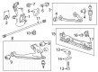
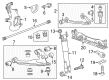
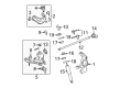
- Q: How to replace the torsion bar and support assembly (bushing style) on Chevrolet Silverado 1500?A:To replace the Torsion Bar and support assembly (Bushing style) first raise and support the vehicle by the frame and avoid the front suspension. Use the j 36202 (Torsion Bar Unloading/Loading Tool) to attach to the adjustment arm and crossmember, take up the tension of the adjustment arm until the load ends on the adjustment bolt and adjuster nut and mark the adjustment bolt and count the turns for unloading. Then, remove the adjustment bolt and adjustment nut from the crossmember, and then remove the j 36202 to unload the Torsion Bar. Slide the Torsion Bar forward to pull the adjustment part, then, take out the bolt of the Torsion Bar crossmember bolt form the weld nut as well as remove the crossmember from the crossmember mount. Lastly, remove the Torsion Bar from the crossmember, which is the left and right Torsion Bar are not interchangeable. For installation, mount the Torsion Bar in a lower Control Arm and bolt it on the cross member in cross member mount. Put in the Torsion Bar crossmember bolt through the weld nut and tighten it to 110 nm (81 lb ft). Then, fix the adjustment arm in the crossmember, then drill fixing holes for adjuster bolt and adjuster nut. Make sure that the Torsion Bar is completely seated in the adjustment arm and then use the j 36202 to load the Torsion Bar by tightening the adjustment arm with some tension. Turn the adjuster bolt to the same number of turns required in turning it to disengage it, then remove the j 36202 from the crossmember. Finally, take off the safety stands and lower the vehicle, and get the z height measurement.


Related Chevrolet Parts
 Chevrolet Drive Shaft
 Chevrolet Wheel Cover
 Chevrolet Leaf Spring
 Chevrolet Steering Knuckle
 Chevrolet Control Arm
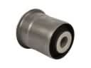 Chevrolet Axle Support Bushings
 Chevrolet Control Arm Bolt
 Chevrolet Control Arm Bumper
 Chevrolet Leaf Spring Shackle
 Chevrolet Ride Height Sensor
 Chevrolet Shock and Strut Boot
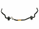 Chevrolet Sway Bar Kit
Browse Chevrolet Torsion Bar by Models
S10 Colorado Tahoe Silverado 1500 Silverado 2500 HD Blazer Astro C1500 C2500 C3500 Express 1500 Express 2500 Express 3500 K1500 K2500 K3500 S10 Blazer Silverado 2500 Silverado 3500 Suburban 1500 Avalanche 1500 Avalanche 2500 C1500 Suburban C2500 Suburban K1500 Suburban K2500 Suburban Silverado 1500 Classic Silverado 1500 HD Silverado 1500 HD Classic Silverado 2500 HD Classic Silverado 3500 Classic Silverado 3500 HD Suburban 2500 Suburban 3500 HD