ChevyParts
My Garage
My Account
Cart
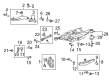
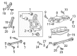
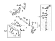
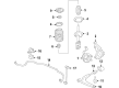
OEM Chevrolet Control Arm
Suspension Arm- Select Vehicle by Model
- Select Vehicle by VIN
Select Vehicle by Model
orMake
Model
Year
Select Vehicle by VIN
For the most accurate results, select vehicle by your VIN (Vehicle Identification Number).
507 Control Arms found


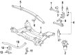
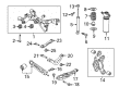
Chevrolet Upper Control Arm, Rear Driver Side Part Number: 23110245
$102.32 MSRP: $174.21You Save: $71.89 (42%)Ships in 1-2 Business DaysProduct Specifications- Other Name: Arm, Rear Axle Control Arm; Suspension Control Arm; Control Arm
- Position: Rear Driver Side
- Replaces: 92236925, 92240558, 22786033


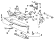
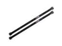
Chevrolet Trailing Arm Part Number: 92246140
$21.75 MSRP: $35.82You Save: $14.07 (40%)Ships in 1-2 Business DaysProduct Specifications- Other Name: Arm Assembly-Rear Suspension Trailing; Suspension Trailing Arm; Arm, Rear Axle Control Arm
- Position: Rear
- Replaces: 92236929


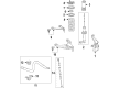
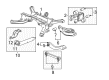
Chevrolet Lower Control Arm, Rear Driver Side Part Number: 84382226
$55.20 MSRP: $94.79You Save: $39.59 (42%)Ships in 1-2 Business DaysProduct Specifications- Other Name: Arm, Rear Axle Control Arm; Control Arm
- Position: Rear Driver Side
- Replaces: 23282356


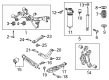
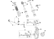
Chevrolet Lower Control Arm, Rear Passenger Side Part Number: 20799880
$211.12 MSRP: $335.19You Save: $124.07 (38%)Ships in 1-2 Business DaysProduct Specifications- Other Name: Arm, Rear Axle Control Arm; Suspension Control Arm and Ball Joint Assembly; Control Arm Assembly; Control Arm
- Position: Rear Passenger Side
- Replaces: 15926334, 25949987, 10339917, 15926336


Chevrolet Lower Control Arm, Passenger Side Part Number: 84376572
$101.25 MSRP: $172.39You Save: $71.14 (42%)Ships in 1-2 Business DaysProduct Specifications- Other Name: Arm, Steering Knuckle Control Arm and Ball Joint Assembly; Suspension Control Arm Assembly.
- Position: Passenger Side
- Replaces: 23421069, 84107268, 84376574, 84362535, 84067512


Chevrolet Lower Control Arm, Passenger Side Part Number: 20799882
$277.26 MSRP: $440.20You Save: $162.94 (38%)Ships in 1-2 Business DaysProduct Specifications- Other Name: Arm, Steering Knuckle Control Arm and Ball Joint Assembly; Suspension Control Arm Assembly.
- Position: Passenger Side
- Replaces: 10339918, 15878396, 15926340


Chevrolet Lower Control Arm, Rear Part Number: 20942237
$54.46 MSRP: $92.72You Save: $38.26 (42%)Ships in 1-2 Business DaysProduct Specifications- Other Name: Arm, Rear Axle Control Arm; Suspension Control Arm; Control Arm
- Position: Rear
- Replaces: 92243845, 92231068, 22743327


Chevrolet Lower Control Arm, Rear Passenger Side Part Number: 20965286
$661.34 MSRP: $887.11You Save: $225.77 (26%)Product Specifications- Other Name: Arm, Rear Axle Control Arm; Control Arm
- Position: Rear Passenger Side


Chevrolet Upper Control Arm, Passenger Side Part Number: 10356431
$240.90 MSRP: $382.45You Save: $141.55 (38%)Ships in 1-2 Business DaysProduct Specifications- Other Name: Arm, Steering Knuckle Upper & Lower Control; Suspension Control Arm; Control Arm
- Position: Passenger Side


Chevrolet Lower Control Arm, Driver Side Part Number: 23490293
$168.17 MSRP: $286.29You Save: $118.12 (42%)Ships in 1-3 Business DaysProduct Specifications- Other Name: Arm, Steering Knuckle Control Arm and Ball Joint Assembly; Suspension Control Arm Assembly.
- Position: Driver Side

Chevrolet Lower Control Arm, Rear Upper Part Number: 87825466
$60.38 MSRP: $103.71You Save: $43.33 (42%)Ships in 1-2 Business DaysProduct Specifications- Other Name: Link Assembly-Rear Suspension Upper Lateral; Arm, Rear Axle Control Arm
- Position: Rear Upper
- Replaces: 84059879, 84988314

Chevrolet Trailing Arm, Rear Passenger Side Part Number: 84175531
$61.60 MSRP: $104.88You Save: $43.28 (42%)Ships in 1-2 Business DaysProduct Specifications- Other Name: Arm Assembly-Rear Suspension Trailing; Arm, Rear Axle Control Arm
- Position: Rear Passenger Side

Chevrolet Lower Control Arm, Passenger Side Part Number: 84198831
$96.15 MSRP: $165.12You Save: $68.97 (42%)Ships in 1-2 Business DaysProduct Specifications- Other Name: Arm, Steering Knuckle Control Arm and Ball Joint Assembly; Suspension Control Arm Assembly.
- Position: Passenger Side
- Replaces: 23421067

Chevrolet Upper Control Arm, Rear Passenger Side Part Number: 10332512
$137.34 MSRP: $226.24You Save: $88.90 (40%)Ships in 1-2 Business DaysProduct Specifications- Other Name: Arm, Rear Axle Control Arm; Control Arm
- Position: Rear Passenger Side

Chevrolet Lower Control Arm, Rear Passenger Side Part Number: 20830781
$149.27 MSRP: $254.19You Save: $104.92 (42%)Ships in 1-2 Business DaysProduct Specifications- Other Name: Arm, Rear Axle Control Arm; Suspension Control Arm; Control Arm
- Position: Rear Passenger Side

Chevrolet Upper Control Arm, Driver Side Part Number: 84289012
$132.08 MSRP: $224.85You Save: $92.77 (42%)Product Specifications- Other Name: Arm, Steering Knuckle Upper & Lower Control; Control Arm
- Position: Driver Side
- Replaces: 23390695

Chevrolet Upper Control Arm, Driver Side Part Number: 84831805
$88.23 MSRP: $138.22You Save: $49.99 (37%)Ships in 1-3 Business DaysProduct Specifications- Other Name: Arm, Steering Knuckle Upper & Lower Control; Control Arm
- Position: Driver Side
- Replaced by: 86271514
Chevrolet Upper Control Arm, Driver Side Part Number: 10356433
$226.34 MSRP: $385.37You Save: $159.03 (42%)Ships in 1-2 Business DaysProduct Specifications- Other Name: Arm, Steering Knuckle Upper & Lower Control; Suspension Control Arm; Control Arm
- Position: Driver Side

Chevrolet Lower Control Arm, Driver Side Part Number: 85561494
$231.63 MSRP: $364.46You Save: $132.83 (37%)Ships in 1-3 Business DaysProduct Specifications- Other Name: Arm, Steering Knuckle Upper & Lower Control
- Position: Driver Side
- Replaced by: 86546939
- Replaces: 84763516
Chevrolet Lower Control Arm, Rear Driver Side Part Number: 20830782
$105.77 MSRP: $240.56You Save: $134.79 (57%)Ships in 1-2 Business DaysProduct Specifications- Other Name: Arm, Rear Axle Control Arm; Suspension Control Arm; Control Arm
- Position: Rear Driver Side
| Page 1 of 26 |Next >
1-20 of 507 Results
Chevrolet Control Arm
Want to cut long-term maintenance and repair costs? Choose OEM Control Arm. Those parts deliver top durability you can trust. On our site, you'll find a huge catalog of genuine Chevrolet parts. Prices are unbeatable, so you can keep more in your pocket. Every OEM Chevrolet Control Arm includes a manufacturer's warranty. You can also get an easy return policy that keeps buying risk free. Fast delivery, get your car on the road quickly. It's simple to search, compare, and order. Stop guessing about quality or fit. Order today and save with parts that last.
Chevrolet Control Arm Parts Questions & Experts Answers
- Q: How to replace the rear axle upper control arm on Chevrolet SSR?A:Vehicle service starts with vehicle lift support and move forward with tire and wheel removal followed by wheelhouse liner removal. Support the rear axle at its designed height (D). First remove the rear axle upper Control Arm to axle mounting bolt and nut and rear axle upper Control Arm to frame mounting bolt followed by disconnecting the rear axle upper Control Arm. To start the installation process begin by mounting the rear axle upper Control Arm and apply a light hand-torque to the frame. Read and adhere to all guidelines found in the fastener notice of service precautions. Fasten the rear axle upper Control Arm to the axle while applying torque of 131 nm (97 ft. Lbs.) to both mounting bolts. Start by removing the rear axle support together with reinstalling the wheelhouse liner and tire and wheel before dropping the vehicle back down.
- Q: How to replace the lower control arm on Chevrolet Malibu?A:Start by elevating and stabilizing your vehicle. Then remove the wheel according to the process. Owners of vehicles with lx9 engines must detach the side transmission mount for the left Control Arm or the Engine Mount for the right Control Arm. Remove the lower Control Arm front bushing to frame bolt followed by removal of lower Control Arm rear bushing to both frame bolts and nuts. Before bolt removal from the Control Arm note its alignment to the Steering Knuckle pinch bolt and discard the pinch bolt. Separate the ball stud from the Steering Knuckle before removing the Control Arm from the vehicle along with the lower Control Arm rear bushing. Install the lower Control Arm rear bushing first before placing the Control Arm between the frame assembly and Steering Knuckle. Start by installing a new ball stud to the Steering Knuckle pinch bolt and performing just a hand tighten. Next install the lower Control Arm front bushing to the frame bolt also performing a hand tighten. The installation requires using fasteners which match the part number for each application according to their specific locations. Are you also told to avoid applying paints or using lubricants or adding corrosion inhibitors on fasteners and joint areas because these substances interfere with torque strength and clamping abilities. Weld the lower Control Arm rear bushing into position by fastening frame bolts and nuts. Secure the ball stud to Steering Knuckle pinch nut at 50 nm (37 lb ft) then rotate the nut 3/4 of a turn before achieving 50 nm (37 lb ft) torques completed with a 60-degree nut rotation. Tighten the first suspension bolt under proper jackstand conditions before setting the front bushing to frame fastener at 50 nm (37 lb ft) and an additional 90 degrees and the rear bushing to frame bolts at 50 nm (37 lb ft) and another 90 degrees. To reinstall the right lower Control Arm you should add the Engine Mount. Installation of the side transmission mount needs to be performed if the left lower Control Arm was removed during service. To finish the installation process simply install the tire and wheel and carefully lower the vehicle.
- Q: How to replace the lower control arm (2500) on Chevrolet Tahoe?A:Starting the lower Control Arm (2500) replacement requires a vehicle lift combined with tire and wheel removal. First detach the stabilizer shaft link from the lower Control Arm before you remove the torsion bars and shock absorber. Move on to unscrew the wheel drive shaft although you'll encounter two different nut designs with and without captured washers. The lower Ball Joint retaining nut requires removal using j 43631 (Ball Joint Separator) and j 45851 (Ball Joint Separator Protector Adapters) to detach the lower Ball Joint from the Steering Knuckle. First loosen the Control Arm nuts with washers from the lower end then unscrew the Control Arm bolts while extracting the Control Arm itself. Position the new lower Control Arm while you secure it with Control Arm bolts along with washers. Secure the lower Control Arm retaining nuts while applying torque to 175 nm (129 lb ft). When installing a new lower Ball Joint into the Steering Knuckle maintain a torque specification between 125 nm (92 lb ft) when it has a captured washer or 70 nm (52 lb ft) with 90 degrees additional torque if it lacks a washer. Place the wheel drive shaft with the shock absorber and torsion bars back in position. After removing the knuckle support and upper Control Arm support you can hook the stabilizer shaft link to the lower Control Arm. After reinstalling the tire and wheel you should remove supports while lowering the car and checking the front end alignment.


Related Chevrolet Parts
 Chevrolet Torsion Bar
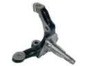 Chevrolet Spindle
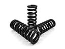 Chevrolet Coil Springs
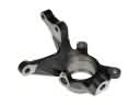 Chevrolet Steering Knuckle
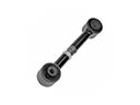 Chevrolet Lateral Link
 Chevrolet Leaf Spring Plate
 Chevrolet Leaf Spring Shackle
 Chevrolet Ride Height Sensor
 Chevrolet Strut Bearing
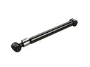 Chevrolet Suspension Strut Rod
 Chevrolet Sway Bar Bracket
 Chevrolet Trailing Arm Bushing
Browse Chevrolet Control Arm by Models
Nova S10 Colorado C10 Tahoe Cruze Malibu Camaro Equinox Impala SS SSR Avalanche Silverado 1500 Silverado 2500 HD Caprice Classic Cobalt Suburban Traverse Blazer HHR Sonic Tracker Volt El Camino K10 Spark Trax Trailblazer Astro Cavalier Corvette C20 Aveo Beretta Bolt EUV Bolt EV C1500 C2500 C30 C3500 Celebrity Chevette City Express Corsica Express 1500 Express 2500 Express 3500 G10 G20 G30 K1500 K20 K2500 K30 K3500 K5 Blazer Lumina Metro Monte Carlo P30 Prizm S10 Blazer Silverado 2500 Sprint Uplander Venture Lumina APV Silverado 3500 Suburban 1500 Trailblazer EXT Avalanche 1500 Avalanche 2500 Aveo5 C10 Suburban C1500 Suburban C20 Suburban C2500 Suburban Captiva Sport Citation II Cruze Limited Impala Limited K10 Suburban K1500 Suburban K20 Suburban K2500 Suburban Malibu Limited P20 R10 R10 Suburban R1500 Suburban R20 R20 Suburban R2500 R2500 Suburban R30 R3500 Silverado 1500 Classic Silverado 1500 HD Silverado 1500 HD Classic Silverado 1500 LD Silverado 1500 LTD Silverado 2500 HD Classic Silverado 3500 Classic Silverado 3500 HD Spark EV Spectrum Suburban 2500 Suburban 3500 HD V10 V10 Suburban V1500 Suburban V20 V20 Suburban V2500 Suburban V30 V3500