ChevyParts
My Garage
My Account
Cart
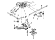
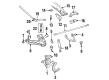
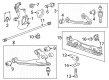
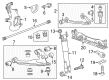
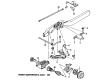
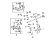
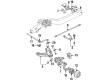
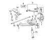
OEM GMC Torsion Bar
Suspension Torsion Bar- Select Vehicle by Model
- Select Vehicle by VIN
Select Vehicle by Model
orMake
Model
Year
Select Vehicle by VIN
For the most accurate results, select vehicle by your VIN (Vehicle Identification Number).
63 Torsion Bars found


GMC Torsion Bar, Front Part Number: 15048312
$257.64 MSRP: $405.40You Save: $147.76 (37%)Ships in 1-3 Business DaysProduct Specifications- Other Name: Bar, Front Torsion
- Position: Front
- Replaced by: 19332932


GMC Torsion Bar, Front Driver Side Part Number: 19330060
$312.71 MSRP: $492.03You Save: $179.32 (37%)Product Specifications- Other Name: Bar, Front Torsion; Ball Joint; Lower Ball Joint; Bar, Front Chassis
- Position: Front Driver Side
- Replaces: 15528965

GMC Torsion Bar, Front Driver Side Part Number: 84745477
$258.71 MSRP: $448.59You Save: $189.88 (43%)Product Specifications- Other Name: Bar-Front Torsion; Bar, Front Chassis
- Position: Front Driver Side
GMC Torsion Bar, Front Passenger Side Part Number: 84745479
$262.36 MSRP: $454.90You Save: $192.54 (43%)Ships in 1-3 Business DaysProduct Specifications- Other Name: Bar-Front Torsion; Bar, Front Chassis
- Position: Front Passenger Side
GMC Torsion Bar, Front Driver Side Part Number: 84745485
$295.06 MSRP: $511.61You Save: $216.55 (43%)Ships in 1-3 Business DaysProduct Specifications- Other Name: Bar-Front Torsion; Bar, Front Chassis
- Position: Front Driver Side
GMC Torsion Bar, Front Passenger Side Part Number: 84745483
$269.89 MSRP: $467.95You Save: $198.06 (43%)Ships in 1-3 Business DaysProduct Specifications- Other Name: Bar-Front Torsion; Bar, Front Chassis
- Position: Front Passenger Side

GMC Torsion Bar, Front Driver Side Part Number: 84301251
$298.62 MSRP: $469.84You Save: $171.22 (37%)Ships in 1-3 Business DaysProduct Specifications- Other Name: Bar-Front Torsion; Bar, Front Chassis
- Position: Front Driver Side
- Replaces: 20883362, 23377391
GMC Torsion Bar, Front Driver Side Part Number: 84745481
$266.15 MSRP: $461.49You Save: $195.34 (43%)Ships in 1-3 Business DaysProduct Specifications- Other Name: Bar-Front Torsion; Bar, Front Chassis
- Position: Front Driver Side


GMC Torsion Bar, Front Driver Side Part Number: 84301245
$259.43 MSRP: $408.22You Save: $148.79 (37%)Product Specifications- Other Name: Bar-Front Torsion; Bar, Front Chassis
- Position: Front Driver Side
- Replaces: 20883356, 23377385

GMC Torsion Bar, Front Driver Side Part Number: 15990699
$110.21 MSRP: $164.00You Save: $53.79 (33%)Ships in 1-3 Business DaysProduct Specifications- Other Name: Bar-Front Torsion (Left-Hand)
- Position: Front Driver Side
GMC Torsion Bar, Front Passenger Side Part Number: 15990700
$110.21 MSRP: $164.00You Save: $53.79 (33%)Ships in 1-3 Business DaysProduct Specifications- Other Name: Bar-Front Torsion (Right-Hand)
- Position: Front Passenger Side


GMC Torsion Bar, Front Passenger Side Part Number: 20784587
Product Specifications- Other Name: Bar-Front Torsion
- Position: Front Passenger Side
- Replaces: 15167960

GMC Torsion Bar, Front Driver Side Part Number: 15945637
Product Specifications- Other Name: Bar-Front Torsion
- Position: Front Driver Side
GMC Torsion Bar, Front Driver Side Part Number: 84301249
$244.12 MSRP: $384.11You Save: $139.99 (37%)Product Specifications- Other Name: Bar-Front Torsion; Bar, Front Chassis
- Position: Front Driver Side
- Replaces: 23377389, 20883360
GMC Torsion Bar, Front Driver Side Part Number: 15100046
Product Specifications- Other Name: Bar-Front Torsion; Bar, Front Chassis
- Position: Front Driver Side
GMC Torsion Bar, Front Driver Side Part Number: 19332967
$67.40 MSRP: $105.58You Save: $38.18 (37%)Product Specifications- Other Name: Bar, Front Torsion; Bar, Front Chassis
- Position: Front Driver Side
- Replaces: 15173584, 20784588
GMC Torsion Bar, Front Passenger Side Part Number: 15945638
Product Specifications- Other Name: Bar-Front Torsion
- Position: Front Passenger Side
GMC Torsion Bar, Front Driver Side Part Number: 20784592
Product Specifications- Other Name: Bar-Front Torsion
- Position: Front Driver Side
- Replaces: 15945639

GMC Torsion Bar, Front Passenger Side Part Number: 15528952
Product Specifications- Other Name: Bar-Front Torsion
- Position: Front Passenger Side

GMC Torsion Bar, Front Passenger Side Part Number: 15051908
Product Specifications- Other Name: Bar-Front Torsion (Right-Hand); Bar, Front Chassis
- Position: Front Passenger Side
| Page 1 of 4 |Next >
1-20 of 63 Results
GMC Torsion Bar
Want to cut long-term maintenance and repair costs? Choose OEM Torsion Bar. Those parts deliver top durability you can trust. On our site, you'll find a huge catalog of genuine GMC parts. Prices are unbeatable, so you can keep more in your pocket. Every OEM GMC Torsion Bar includes a manufacturer's warranty. You can also get an easy return policy that keeps buying risk free. Fast delivery, get your car on the road quickly. It's simple to search, compare, and order. Stop guessing about quality or fit. Order today and save with parts that last.
GMC Torsion Bar Parts Questions & Experts Answers
- Q: How to replace the torsion bar and support assembly (Link Style) on GMC Sierra 1500?A:Vehicle support starts with lifting and frame stabilization above the front suspension. Handle the torsion bars with care while installing new parts due to coating damage that results in shortened lifespan. Place the j 36202 (Torsion Bar Unloading/Loading Tool) onto the adjustment arm and support assembly. You should verify that the adjustment bolt and adjuster nut become loose when you steadily increase the tension on the adjustment arm while noting the total number of turns it takes to make the adjustment bolt loose. After removing the adjustment bolt and adjuster nut from the support assembly continue by removing the j 36202 tool to unload the Torsion Bar. After sliding the Torsion Bar forward remove the adjustment arm from the support assembly followed by upper link mounting bolt and nut from the link to remove the Torsion Bar support assembly. Due to their design differences torsion bars from the left and right sides do not match each other. To install the Torsion Bar position it first in the lower Control Arm and support assembly but always follow fastener cautions. Tighten the upper link mounting nut and bolt to 95 nm (70 lb ft) in the link's assembly . The next step requires installation of the adjustment arm into the support assembly before installing the adjuster bolt and adjustment nut. Push the Torsion Bar all the way back until it is completely seated in the adjustment arm before reattaching the support assembly and j 36202 bolt. The reference marks must match up before tightening the adjuster bolt to match the previous rotation count. Remove j 36202 and remove the safety stand before lowering the vehicle to measure z height.
- Q: How to service and repair the torsion bar on GMC Safari?A:The servicing procedure for torsion bars begins by raising the vehicle to necessary height. Begin by removing both adjustment assemblies from the torsion bar and note down the bolt adjustment position. The Torsion Bar Unloading/Loading Tool (J 36202) require users to increase adjustment arm tension so they can detach the adjustment bolt and retaining nut before relocating the tool to a different position. To remove the torsion bar adjustment arm start by moving the torsion bar forward then detach the adjustment arm. Mark L for left and R for right on the front ends of the torsion bars so you identify the distinct bars for each side. Slide the torsion bars partway back through the crossmember before continuing. Place the dropped front end of the torsion bar down before moving it forward. During installation remember to indicate L or R on the torsion bar front end. Apply axle grease to all torsion bar elements before installing the components. First add grease to both the adjuster bolts and adjuster arms. When the adjuster arm installation is complete it must maintain a 1.0-2.0 mm (0.04-0.10 inch) gap between its rear side and the rear side of the torsion bar. Utilize the Torsion Bar Unloading/Loading Tool (J 36202) to create tension on the torsion bar when you install the adjustment retaining nut and adjustment bolt. Install the retaining nut and adjustment bolt before setting the adjustment bolt to its marked position and releasing tension only when the bolt absorbs the full load torque. Lower the vehicle after removing the Torsion Bar Unloading/Loading Tool (J 36202) to verify Z height measurement.
- Q: How to replace the torsion bar on GMC Canyon?A:To remove the Torsion Bar, it is necessary first, raise and support the vehicle. Let the front suspension settle in the rebound position and note the number of turns it takes to release the adjuster bolt, making a note to use exactly that number of turns for re-assembly. Remove the adjuster bolt, spacer, and adjuster nut, keeping in mind that the torsion bars have specific applications for the left and right sides of the vehicle. Then, swap out the adjustment arms and torsion bars as a complete unit by pulling it to the rear to release the lower Control Arm. Install: place adjustment arms and torsion bars relative to its original position, attach adjustment arm to Torsion Bar, and slide Torsion Bar forward until it completes entering into lower Control Arm. Mount the adjuster bolt, spacer, and adjuster nut and lower the vehicle and measure the z-height to the trim height specifications.


Related GMC Parts
 GMC CV Joint
 GMC Steering Knuckle
 GMC Axle Beam Mount
 GMC Axle Support Bushings
 GMC Coil Spring Insulator
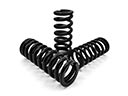 GMC Coil Springs
 GMC Control Arm Bushing
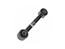 GMC Lateral Link
 GMC Leaf Spring Shackle
 GMC Shock And Strut Mount
 GMC Shock and Strut Boot
 GMC Sway Bar Bushing
Browse GMC Torsion Bar by Models
Sierra 1500 Yukon Canyon Sierra 2500 HD Sonoma Typhoon Syclone C1500 Jimmy K1500 S15 S15 Jimmy Safari Savana 2500 Savana 3500 Sierra 2500 Sierra 3500 C2500 C3500 K2500 K3500 Savana 1500 Yukon XL 1500 C1500 Suburban C2500 Suburban K1500 Suburban K2500 Suburban Sierra 1500 Classic Sierra 1500 HD Sierra 1500 HD Classic Sierra 2500 HD Classic Sierra 3500 Classic Sierra 3500 HD Yukon XL 2500