ChevyParts
My Garage
My Account
Cart
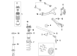
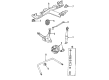
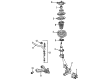
OEM Cadillac Wheel Bearing
Hub Bearing- Select Vehicle by Model
- Select Vehicle by VIN
Select Vehicle by Model
orMake
Model
Year
Select Vehicle by VIN
For the most accurate results, select vehicle by your VIN (Vehicle Identification Number).
75 Wheel Bearings found


Cadillac Hub & Bearing, Front Part Number: 13585439
$108.61 MSRP: $203.96You Save: $95.35 (47%)Ships in 1-2 Business DaysProduct Specifications- Other Name: Bearing Assembly-Front Wheel; Wheel Hub Repair Kit; Wheel Bearing; Axle Bearing; Wheel Hub; Hub, Front Wheel
- Position: Front


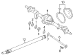
Cadillac Wheel Bearing, Rear Part Number: 88927028
$26.51 MSRP: $49.79You Save: $23.28 (47%)Ships in 1-2 Business DaysProduct Specifications- Other Name: Bearing, Rear Wheel; Axle Bearing; Axle Bearings; Shaft Bearings; Housing Bearing; Bearing; Bearing, Transmission Countershaft Gear
- Position: Rear
- Replaces: 15595140


Cadillac Hub & Bearing, Rear Part Number: 25954415
$280.83 MSRP: $549.85You Save: $269.02 (49%)Ships in 1-2 Business DaysProduct Specifications- Other Name: Hub Assembly-Rear Wheel (W/Bearing); Wheel Hub Repair Kit; Axle Bearing.; Hub; Hub, Front Wheel; Hub, Rear Wheel
- Position: Rear
- Replaced by: 19421348


Cadillac Hub & Bearing, Front Part Number: 13589554
$87.78 MSRP: $170.36You Save: $82.58 (49%)Ships in 1-2 Business DaysProduct Specifications- Other Name: Bearing Assembly-Front Wheel; Wheel Hub Repair Kit; Wheel Bearing; Axle Bearing; Wheel Hub
- Position: Front
- Replaced by: 13552403


Cadillac Hub & Bearing, Front Part Number: 12413103
$106.31 MSRP: $198.37You Save: $92.06 (47%)Ships in 1-2 Business DaysProduct Specifications- Other Name: Hub, Front Wheel; Wheel Bearing and Hub Assembly; ABS Sensor; Repair Kit.; Front Speed Sensor
- Position: Front


Cadillac Wheel Bearing Part Number: 9436881
$80.31 MSRP: $145.36You Save: $65.05 (45%)Ships in 1-3 Business DaysProduct Specifications- Other Name: Bearing, Differential; Differential Pinion Bearing; Differential Bearing; Axle Bearings; Shaft; Inner; Side; Differential Gear; Front Wheel; Rear Wheel; Nut.


Cadillac Front Hub & Bearing Assembly Part Number: 7470511
$199.93 MSRP: $361.87You Save: $161.94 (45%)Ships in 1-2 Business DaysProduct Specifications- Other Name: Hub, Front Wheel; Wheel Bearing & Hub Assembly; Repair Kit; Axle Bearing.; Hub & Bearing; Hub & Bearing Assembly; Rotor Hub & Bearing; Hub
- Position: Front


Cadillac Wheel Bearing Part Number: 457049
$24.87 MSRP: $45.03You Save: $20.16 (45%)Ships in 1 Business DayProduct Specifications- Other Name: Bearing, Front Wheel Outer; Axle Bearing; Wheel Bearings; Front Wheel Bearing; Front Bearing; Outer Wheel Bearing; Outer Bearing; Bearing

Cadillac Rear Speed Sensor Part Number: 89047669
$266.32 MSRP: $477.69You Save: $211.37 (45%)Ships in 1-3 Business DaysProduct Specifications- Other Name: Hub, Rear Wheel; Wheel Bearing and Hub Assembly; Wheel Bearing; Axle Bearing; ABS Sensor; Wheel Hub; Hub & Bearing
- Position: Rear

Cadillac Hub Assembly Part Number: 13536121
$131.19 MSRP: $235.32You Save: $104.13 (45%)Product Specifications- Other Name: Hub, Rear Wheel (W/Bearing); Wheel Hub; Rear Hub & Bearing; Hub, Rear Wheel
- Replaced by: 13549865

Cadillac Bearing Assembly, Front Part Number: 7470014
$140.68 MSRP: $275.44You Save: $134.76 (49%)Ships in 1-2 Business DaysProduct Specifications- Other Name: Hub Kit, Front Wheel; Wheel Bearing & Hub Assembly; Wheel Hub Repair Kit; Axle Bearing.; Front Hub & Bearing; Hub & Bearing; Hub & Bearing Assembly; Bearing; Hub, Front Wheel
- Position: Front

Cadillac Hub & Bearing, Front Part Number: 19352506
$176.72 MSRP: $319.85You Save: $143.13 (45%)Ships in 1-2 Business DaysProduct Specifications- Other Name: Hub Assembly, Front Wheel (W/Wheel Speed Sensor); Wheel Bearing & Hub Repair Kit.; Hub, Front Wheel
- Position: Front
- Replaces: 15816313

Cadillac Hub Assembly, Rear Part Number: 13544387
$84.90 MSRP: $166.22You Save: $81.32 (49%)Ships in 1-3 Business DaysProduct Specifications- Other Name: Hub Assembly-Rear Wheel; Rear Hub & Bearing; Hub & Bearing Assembly
- Position: Rear
- Replaced by: 13552420
Cadillac Hub Assembly, Front Part Number: 13546938
$86.54 MSRP: $167.96You Save: $81.42 (49%)Product Specifications- Other Name: Hub Assembly-Front Wheel; Front Hub & Bearing; Rear Hub & Bearing; Hub & Bearing; Hub & Bearing Assembly
- Position: Front
- Replaces: 13500572, 13507016, 13502829, 13590795, 13580686, 13585466, 13526966, 13583479

Cadillac Hub & Bearing, Front Part Number: 22859843
$125.51 MSRP: $243.60You Save: $118.09 (49%)Ships in 1 Business DayProduct Specifications- Other Name: Hub, Front Wheel; Wheel Bearing & Hub Assembly; Repair Kit; Axle Bearing.
- Position: Front
- Replaced by: 13564982

Cadillac Wheel Bearings, Front Inner Part Number: 15595151
$75.48 MSRP: $141.74You Save: $66.26 (47%)Ships in 1-2 Business DaysProduct Specifications- Other Name: Bearing, Front Wheel Inner; Wheel Bearing; Axle Bearing; Inner Bearing
- Position: Front Inner

Cadillac Front Hub Part Number: 84856653
$241.51 MSRP: $472.84You Save: $231.33 (49%)Ships in 1-2 Business DaysProduct Specifications- Other Name: Hub Assembly-Front Wheel (W/ Bearing & Wheel Speed Sensor); Wheel Hub Repair Kit; Wheel Bearing; Axle Bearing; Wheel Hub; Hub & Bearing; Hub, Front Wheel
- Position: Front
- Replaces: 10393170, 20883242, 84356642, 25819677, 22841380

Cadillac Hub Assembly, Front Part Number: 13535013
$96.72 MSRP: $172.72You Save: $76.00 (44%)Ships in 1-3 Business DaysProduct Specifications- Other Name: Hub Assembly-Front Wheel; Front Hub & Bearing; Rear Hub & Bearing; Hub & Bearing
- Position: Front
- Replaced by: 13544844

Cadillac Hub & Bearing Assembly, Rear Part Number: 25716676
$407.89 MSRP: $731.64You Save: $323.75 (45%)Product Specifications- Other Name: Hub Assembly-Rear Wheel; Wheel Bearing; Axle Bearing; Hub, Rear Wheel
- Position: Rear
- Replaces: 25683107

Cadillac Hub & Bearing, Front Part Number: 25678854
$591.43 MSRP: $1065.64You Save: $474.21 (45%)Product Specifications- Other Name: Hub Assembly-Front Wheel (W/Wheel Speed Sensor); Wheel Hub Repair Kit; Wheel Bearing; Axle Bearing; Wheel Hub; Hub, Front Wheel
- Position: Front
| Page 1 of 4 |Next >
1-20 of 75 Results
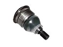
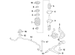
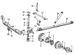
Cadillac Wheel Bearing
Want to cut long-term maintenance and repair costs? Choose OEM Wheel Bearing. Those parts deliver top durability you can trust. On our site, you'll find a huge catalog of genuine Cadillac parts. Prices are unbeatable, so you can keep more in your pocket. Every OEM Cadillac Wheel Bearing includes a manufacturer's warranty. You can also get an easy return policy that keeps buying risk free. Fast delivery, get your car on the road quickly. It's simple to search, compare, and order. Stop guessing about quality or fit. Order today and save with parts that last.
Cadillac Wheel Bearing Parts Questions & Experts Answers
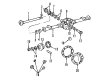
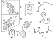
- Q: How to replace the rear wheel bearing/hub on Cadillac CTS?A:You must lift up the vehicle for this work to begin. Take off the tire and wheel then remove the brake rotor at the back. You should remove the wheel drive shaft nut plus disconnect the abs sensor electrical connector and its backing plate connection. Take out the parking brake cable bracket bolts from the knuckle then detach the parking brake cable bracket. Apply the Wheel Bearing/hub axel remover tool (J 45859 or equivalent) onto the Wheel Bearing/hub to release the driving shaft connection. Use a Wheel Hub remover tool to remove Wheel Bearing/hub bolts because some bearings may need full axial movement before disengagement from the drive axle. Lift out the Wheel Bearing/hub and backing plate from the knuckle while also taking away the axle remover (J 45859) or comparable tool. Position the Wheel Bearing/hub along with the backing plate onto the knuckle and put in the bolts afterwards. Tighten the bolts to 125 n.m (92 lb ft). Secure the parking brake cable bracket to its location and bolt down all components at 60 n.m (44 lb ft). Plug the abs sensor electrical connector to the backing plate and main connector. Fasten the new wheel drive shaft nut to 160 n.m tension before installing the brake rotor and tire assembly. Finally, lower the vehicle.
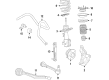
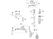
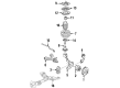
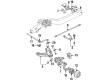
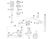
- Q: How to service the front wheel bearing and hub on Cadillac Escalade?A:Before servicing the front Wheel Bearing and hub, you need to raise the vehicle and hold it up using suitable safety stands. After taking off the wheel and tire, use a wire to hold the brake caliper and avoid harming the Brake Line. Cover the inside and outside of the c/v joint boots with shop towels to prevent them from being damaged during the process. After that, remove the brake caliper, drive axle nut, washer and brake rotor. When the tie rod nut is removed, disconnect the Tie Rod End from the knuckle and place the hub and bearing assembly on the side of the hub bolt so it does not get dirty. Place a puller on the hub and bearing assembly to release it and then use a socket or ratchet to unscrew the bolts that hold down the halfshaft and the splash shield before you remove the shield. Place a jack stand beneath the lower Control Arm, remove the upper and lower Ball Joint nuts and detach the ball joints from the knuckle with j 36607 before you take out the knuckle and seal. While installing, insert the seal into the j 36605 first, then connect the ball joints to the knuckle, install the nuts on the studs and tighten the lower one to 128 nm (94 ft. Lbs.) and the upper one to 100 nm (74 ft. Lbs.) without applying too much torque. Put on the new cotter pins, fit and bolt in the splash shield and tighten them to 26 nm (19 ft. Lbs.). Treat the seals inside the steering knuckle with grease, slip on the half shaft, place the hub and bearings assembly, arrange the holes for evenness and tighten the bolts to 180 nm (133 ft. Lbs.). Attach the Tie Rod End to the knuckle, fasten it using the nut and tighten it to 48 nm (35 ft. Lbs.). Then, set the washer, followed by the drive axle nut that you should tighten to 225 nm (165 ft. Lbs.). The last step is to add the rotor and Brake Calipers, attach the tire and wheel setup, take down the jack stand, lower the vehicle and make sure the trim height is correct and alter it if needed.
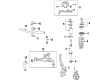
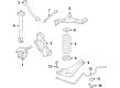
- Q: How to replace the front wheel bearing and hub on Cadillac XLR?A:You have to lift and stabilize the vehicle before taking out the tire and wheel for front Wheel Bearing and hub replacement. Use a single step to disconnect both wheel speed sensor and brake caliper components from the harness. Support the lower Control Arm with a jackstand after removing its connection to the stabilizer shaft link. Run j 42188 tool to disconnect the outer tie rod ball stud from the Steering Knuckle and the lower ball joint stud. You should now take out the hub and bearing assembly from the Steering Knuckle by removing its Wheel Hub mounting bolts. Put the hub and bearing assembly into the Steering Knuckle then secure its Wheel Hub mounting bolts by torquing them to 130 nm (96 lb ft). Put back the lower Control Arm ball stud to Steering Knuckle then take out the jackstand before putting the outer tie rod ball stud into position. Connect the wiring harness of the wheel speed sensor and bolt the stabilizer shaft link to the lower Control Arm. Put back the wheel assembly with tire and brake components. Let the vehicle down to its normal position.