ChevyParts
My Garage
My Account
Cart
OEM Chevrolet Fuel Injector
Gas Injector- Select Vehicle by Model
- Select Vehicle by VIN
Select Vehicle by Model
orMake
Model
Year
Select Vehicle by VIN
For the most accurate results, select vehicle by your VIN (Vehicle Identification Number).
212 Fuel Injectors found


Chevrolet Injector Part Number: 55565970
$36.17 MSRP: $69.62You Save: $33.45 (49%)Ships in 1 Business DayProduct Specifications- Other Name: Injector, Fuel Injection; Gasoline Injector; Fuel Injector


Chevrolet Injector Part Number: 25195224
$43.94 MSRP: $82.52You Save: $38.58 (47%)Ships in 1-2 Business DaysProduct Specifications- Other Name: Injector Kit, Fuel Injection; Fuel Injector; Injector, Fuel Injection
- Replaces: 25185231


Chevrolet Injector Part Number: 12606110
$60.28 MSRP: $169.72You Save: $109.44 (65%)Ships in 1 Business DayProduct Specifications- Other Name: Injector Kit, Fuel Injection; Fuel Injector; Injector, Fuel Injection
- Replaces: 12582704

Chevrolet Injector Part Number: 89017586
$38.01 MSRP: $121.56You Save: $83.55 (69%)Ships in 1-2 Business DaysProduct Specifications- Other Name: Injector Kit, Fuel Injection; Gasoline Injector; Fuel Injector

Chevrolet Injector Part Number: 19210900
$399.51 MSRP: $737.27You Save: $337.76 (46%)Ships in 1-2 Business DaysProduct Specifications- Other Name: Injector Kit, Fuel Injection; Common Rail Injector; Fuel Injector

Chevrolet Injector Part Number: 89017704
$90.23 MSRP: $163.32You Save: $73.09 (45%)Ships in 1-2 Business DaysProduct Specifications- Other Name: Injector Kit, Fuel Injection; Gasoline Injector; Fuel Injector

Chevrolet Injector Part Number: 17112249
$137.76 MSRP: $247.10You Save: $109.34 (45%)Ships in 1-3 Business DaysProduct Specifications- Other Name: Fuel Injector
- Replaced by: 19110533
Chevrolet Injector Part Number: 12655674
$31.45 MSRP: $59.06You Save: $27.61 (47%)Ships in 1-2 Business DaysProduct Specifications- Other Name: Injector, Fuel Injection; Fuel Injector
Chevrolet Injector Part Number: 17111928
$150.31 MSRP: $269.62You Save: $119.31 (45%)Ships in 1-3 Business DaysProduct Specifications- Other Name: Fuel Injector
- Replaced by: 19110532
Chevrolet Injector Part Number: 17111799
$62.96 MSRP: $196.46You Save: $133.50 (68%)Ships in 1-2 Business DaysProduct Specifications- Other Name: Fuel Injector
- Replaced by: 19244619
Chevrolet Injector Part Number: 12721341
$83.93 MSRP: $149.88You Save: $65.95 (44%)Ships in 1-3 Business DaysProduct Specifications- Other Name: Injector Assembly, Direct Fuel; Injector, Fuel Injection
Chevrolet Injector Part Number: 12732622
$116.07 MSRP: $208.20You Save: $92.13 (45%)Ships in 1-2 Business DaysProduct Specifications- Other Name: Injector Kit-Multiport Fuel; Injector Kit, Fuel Injection
- Replaces: 12726900
Chevrolet Injector Part Number: 19420033
$413.38 MSRP: $741.48You Save: $328.10 (45%)Ships in 1-3 Business DaysProduct Specifications- Other Name: Injector Kit, Fuel Injection; Fuel Injector; Injector, Fuel Injection
- Replaces: 22991067
Chevrolet Injector Part Number: 12709231
$48.75 MSRP: $87.06You Save: $38.31 (44%)Ships in 1-2 Business DaysProduct Specifications- Other Name: Injector Assembly-Direct Fuel; Injector, Fuel Injection


Chevrolet Injector Part Number: 12703612
Product Specifications- Other Name: Injector Kit-Multiport Fuel (High Flow); Fuel Injector; Injector Kit, Fuel Injection
- Replaces: 12661031, 12668655, 12672374, 12684130, 12686277

Chevrolet Throttle Body Part Number: 17091078
Product Specifications- Other Name: TBI; EGR Valve; Throttle Body Kit; Injector, Throttle Body/Carburetor
Chevrolet Injector Part Number: 19420335
$55.45 MSRP: $86.86You Save: $31.41 (37%)Product Specifications- Other Name: Injector Kit, Multiport (Low Flow); Fuel Injector; Injector Kit, Fuel Injection
- Replaces: 12672372, 12661030, 12684131, 12710479, 12703613, 12686275, 12668653
Chevrolet Injector Part Number: 17109952
Product Specifications- Other Name: Injector Kit, Fuel Injection; Fuel Injector
Chevrolet Injector Part Number: 17109953
Product Specifications- Other Name: Injector Kit, Fuel Injection; Fuel Injector
Chevrolet Injector Part Number: 17124251
Product Specifications- Other Name: Injector Kit, Multiport Fuel; Fuel Injector; Injector Kit, Fuel Injection
- Replaces: 17121909
| Page 1 of 11 |Next >
1-20 of 212 Results
Chevrolet Fuel Injector
Want to cut long-term maintenance and repair costs? Choose OEM Fuel Injector. Those parts deliver top durability you can trust. On our site, you'll find a huge catalog of genuine Chevrolet parts. Prices are unbeatable, so you can keep more in your pocket. Every OEM Chevrolet Fuel Injector includes a manufacturer's warranty. You can also get an easy return policy that keeps buying risk free. Fast delivery, get your car on the road quickly. It's simple to search, compare, and order. Stop guessing about quality or fit. Order today and save with parts that last.
Chevrolet Fuel Injector Parts Questions & Experts Answers
- Q: How to clean the fuel injector on Chevrolet Colorado?A:The required tools for Fuel Injector cleaning consist of fuel line shut-off adapters (J 37287), Fuel Injector cleaner (J 38500-A), 3/8 fuel line shut-off valve (J 42873-1), 5/16 return pipe shut-off valve (J 42873-2), 3/8 fuel pipe shut-off valve (J 42964-1) and 5/16 fuel pipe shut-off valve (J 42964-2). Use gm top-engine cleaner p/n 12346535 in the us but canadian dealers should use p/n 992872 while respecting a cleaning solution concentration up to 10 percent. Start your procedure by acquiring two tanks containing the Fuel Injector cleaner product designated j 38500-a and verify that the bottom valve of the canister remains sealed. The j 38500-a requires two pre-stacked gm top-engine cleaner containers for us dealers but canadian dealers should measure then fill with 48 ml of top-engine cleaner. The mixture requires 96 ml top-engine cleaner blended with 864 ml regular unleaded gasoline for alternative brand use. Regular unleaded gasoline must be put into the cleaning tank of the tool using all instructions included with the tool. The vehicle Fuel Pump needs disabling and specific shut-off valves should secure the fuel feed and return line where it meets the Fuel Rail. Use the j 38500-a to connect with the vehicle Fuel Rail before applying 510 kpa (75 psi) pressure. The j 38500-a should be unconnected once the engine stops idling before you return the Fuel Pump relay and oil pressure switch connector back into place. After disconnecting the shut-off valves proceed to reconnect the fuel lines and let the vehicle start for 2 more minutes with an idle. Run a second injector balance test to measure fuel pressure drops from all injectors before you change any unit which shows more than 15 kpa (2 psi) decline. One ounce of port Fuel Injector cleaner, gm p/n 12345104 (Canadian P/N 10953467), should be added to the fuel tank for each gallon of gasoline while providing instructions to the customer for fuel brand changes and gm port Fuel Injector cleaner use as maintenance for every 5000 km (3,000 mi). Then conduct a road test to confirm the customer concern is solved.
- Q: How to replace a fuel injector on Chevrolet Malibu?A:The first step when replacing fuel injectors requires draining the fuel system pressure. You should start by removing the Fuel Rail then unclipping the retaining clips before taking out the fuel injectors from the rail. You must detach both Fuel Injector O-Ring components starting with the upper segment followed by the lower segment. The process of new injector installation requires proper flow rate calibration for each component while selecting the appropriate part number. Position the Fuel Injector upper o-ring along with the lower o-ring while carefully placing the brown o-ring at the bottom followed by using an o-ring back up for correct o-ring positioning on the Fuel Injector. Install the Fuel Injector onto the Fuel Rail after which the retaining clips must be used to secure it. Fasten the Fuel Rail back into place before closing the fuel filler cap securely. Check for fuel leaks by turning on the ignition for two seconds followed by waiting ten seconds with the ignition off then recheck for any fluid drippage upon turning on the ignition.
- Q: How to service and repair the fuel injector on Chevrolet S10?A:A vehicle operator should start service or repair work on fuel injectors by unscrewing the fuel filler cap so vapor pressure in the Fuel Tank decreases. The pcv clean air tube should be detached from the air inlet duct before removing the resonator and air inlet duct from the Throttle Body. Disconnect the central sequential fuel injection (CSFI) fuel metering body electrical connector while you detach the Brake Booster Vacuum Hose along with its connector from the Intake Manifold. Disconnect Spark Plug Wires from Distributor Cap cylinders 1, 3, and 5 while removing the Intake Manifold fuel line bolt at its rear position. The technician should first depressurize the fuel system before unthreading the nuts and clamp from the fuel pipe while checking the correct placement of the fuel pipe o-rings and washers and spacers. Begin installing the j 44466-12 and j 44466-13 to the metering body before tightening the hardware, then move onto hooking up the j 44466-11 and clamp followed by the j 44466-13 to the fuel pipe connection point. Place the j 41413 instrument on the tank valve to close it while discarding the regulator assembly and installing the j 44466-10 hose to the j 41413 tank. Ensure the metering body electrical connector receives connections from the j 39021, j 39021-210, and j 39021-301 while using the j 39021 amperage selector switch to set an output of 0.5 amps. Turn on the valves at the tank and j 44466-10 to build up fuel system pressure before maintaining at least 150 psi minimum pressure. Check that each injector operates properly by using the j 39021 as you observe the pressure drops. Stop the pressure flow at the j 41413 tank through its pressure valve and release all pressure at the j 44466-10. Install the pcv fresh air tube while disconnecting the j 44466-10 from j 44466-12 and j 41413 and removing j 39021-301, j 39021-210, j 39021 from the metering body. Proceed with connecting the electrical connector first followed by attaching the Brake Booster Vacuum Hose before reconnecting ignition wires. Secure the resonator and air intake duct before obtaining the j 38500-a which requires closure of the canister valve at its bottom. Place top engine cleaner gm p/n 12346535 into the canister before filling it with regular unleaded gasoline then suspend the j 38500-a. Insert the hose from j 38500-a into the service port of j 44466-12. Open the bottom valve of j 38500-a and establish shop air delivery at 75 psi. Follow these steps: make the j 38500-a empty while the vehicle runs then stop shop air delivery and allow the j 38500-a pressure to decrease. Disconnect the hose from the j 44466-12 before performing another pcv clean air tube, resonator, and ignition wires removal. After bleaching j 44466-12 of residual pressure, workers must remove j 44466-13 and j 44466-12 from the metering body before installing j 44466-13 followed by the clamp and j 44466-11 onto the fuel pipe. Lock and tighten the fuel pipe to the metering body using both clamp and nuts at 3 n.m (27 lb ft). Threadlock gm p/n 12345382 must be applied to the fuel pipe bolt before tightening it to 6 n.m (53 lb ft). The service continues with installation of ignition wires after fitting the Brake Booster Vacuum Hose and the resonator and the pcv clean air tube. A proportionate amount of port Fuel Injector cleaner from gm p/n 12345515 in canada must be added to each standard gallon of gasoline present inside the Fuel Tank. Put on the Fuel Tank filler cap and start the engine then inspect for leakage at the Fuel Tank. Use a tech ii scan tool to verify that powertrain dtc codes are stored and clear them if required before ensuring the customer switches to new fuel brands.


Related Chevrolet Parts
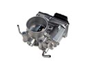 Chevrolet Throttle Body
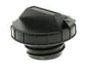 Chevrolet Gas Cap
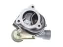 Chevrolet Turbocharger
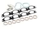 Chevrolet Intake Manifold Gasket
 Chevrolet Fuel Tank Sending Unit
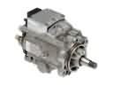 Chevrolet Fuel Injection Pump
 Chevrolet Fuel Injector O-Ring
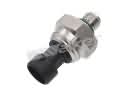 Chevrolet Fuel Pressure Sensor
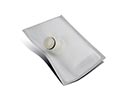 Chevrolet Fuel Pump Strainer
 Chevrolet Fuel Pump Wiring Harness
 Chevrolet Fuel Tank Lock Ring
 Chevrolet Vapor Pressure Sensor
Browse Chevrolet Fuel Injector by Models
Nova S10 Colorado C10 Tahoe Cruze Malibu Camaro Equinox Impala SS SSR Avalanche Silverado 1500 Silverado 2500 HD Caprice Classic Cobalt Suburban Traverse Blazer HHR Sonic Tracker Volt El Camino K10 Spark Trax Trailblazer Astro Cavalier Corvette C20 Aveo Beretta C1500 C2500 C30 C3500 Celebrity City Express Corsica Express 1500 Express 2500 Express 3500 G10 G20 G30 K1500 K20 K2500 K30 K3500 K5 Blazer Lumina Metro Monte Carlo Prizm S10 Blazer Silverado 2500 Sprint Uplander Venture Lumina APV Silverado 3500 Suburban 1500 Trailblazer EXT Avalanche 1500 Avalanche 2500 Aveo5 C10 Suburban C1500 Suburban C20 Suburban C2500 Suburban Captiva Sport Citation II Cruze Limited Impala Limited K10 Suburban K1500 Suburban K20 Suburban K2500 Suburban R10 R10 Suburban R1500 Suburban R20 R20 Suburban R2500 R2500 Suburban R30 R3500 Silverado 1500 Classic Silverado 1500 HD Silverado 1500 HD Classic Silverado 1500 LTD Silverado 2500 HD Classic Silverado 3500 Classic Silverado 3500 HD Spectrum Suburban 2500 Suburban 3500 HD V10 V10 Suburban V1500 Suburban V20 V20 Suburban V2500 Suburban V30 V3500